Hi all,
I just completed a simple little ECL82 PP headphone amp today. You know that moment of trepidation when you first throw the switch - well it worked first time and sounds prity good to boot. No hum to speak of either. Now that a never before event as usually my builds need extensive debugging.
I need to tidy things up a bit and close the case in the next couple of days, and then I will post a picture.
I will draw up a schematic as it includes quite a few interesting feature - such as microphone transformer as input step down phase splitter, Triode front end LTP with grid leak bias, and fully differential output stage with garter bias for perfect current balance.
Shoog
What is garter bias?fully differential output stage with garter bias
What did you use for an OP tranny?
One trick I've heard of is just to buid a normal OP stage, including transformer to match the tube to 8 ohm, and to connect an 8 ohm 'dummy load' resistor across the output. You then connect the phones across the dummy load. (It's done like that to avoid having to find a rare (and rather expensive) headphone tranny.)
Garter bias is described in this Tubecad article. It seems to work rather well.
http://www.tubecad.com/2005/May/blog0046.htm
The only difference in my implementation is that the bypass caps cathodes are tied together and the node is referenced to earth via a 1meg resistor - hence differential.
I am using a mains toroidal as the output transformer - seems to be working and is fairly immune to impedance mismatch.
Since moving it to my main system I can hear a 50hz hum in one channel. On my workshop test rig the radio hiss was masking it. Very nice soft sound overall. Its the first time I have used the ECL82 and not been disappointed by its harshness.
Shoog
So heres the schematic.
Still got a small amount of 50hz hum - equal on both channels and just noticable with nothing playing. Any ideas where to start looking for the source. Have the circuit earth isolated from mains earth by a 100R resistor paralleled with back to back diodes and a small cap.
Will post a picture when I work out how to get Suse Linux to recognise my digital camera.
Of course this is a trial run to test out the concepts before enbarking on my clone of Gary Pimms Tabor amp.
Shoog
Attachments
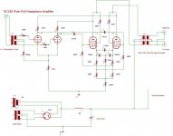
Glad you spotted that the effective value of the bypass cap was 500uf and not 1000uf. To be honest I chose them based on what I had in the parts bin. You can derive the correct value by doing a standard cathode bypass calculation and doubling it.
The tube used is an ECL82 which is a combined triode pentode.
Shoog
The tube used is an ECL82 which is a combined triode pentode.
Shoog
I can only point you to the tubecad article where he does a test with grossly mismatched tubes and gets within 20% (I think). The man was a genus in an age when engineering was respected.
It works and works well. If it didn't I would be experiencing massive power supply hum as the power supply is very minimal. I am so impressed that I am seriously thinking of using it over Lm317 CCS in my Tabor clone. The only downside is the need to burn up twice the bias voltage. Since in both this design and my Tabor clone I need to burn up cathode voltage to get it to work - it suites me fine. Of course nominally a LM317 CCS should perform better on paper at least, but resistors are more robust and don't need heatsinks.
If I wanted to I could drop the input transformer and use this as a 7watt PP amp. Still most of the advantages of this circuit would be lost in the bargin.
Shoog
True, it's CMRR is strongly in evidence if it is cancelling hum from your admittedly minimalist power supply. That cross-coupling of grids to cathodes shows up in Western Electric designs. I hadn't heard about the Tabor but now that Gary Pimm has taken down his website it's not possible to find out much (and it was never particularly well documented.) Are you using 1624s in your Tabor clone?
No I have a rake of 807's (electrically identical but indirectly heated) so thats what I will be using. Just waiting for the bases and some 6AU6's. I have great hopes for this design.
Was it yourself who went for the Vacuum State 300B amp in the end. If so, how did it turn out.
Shoog
Was it yourself who went for the Vacuum State 300B amp in the end. If so, how did it turn out.
Shoog
Yes, I have in fact just finished building a pair of DPA-300B power amps. I'm pleased with the way they turned out, but I hasten to add that they turned out as well as they did, in my view, because I put a fair bit of nous into building them. Allen's kits are a bit spotty: some of the construction is brilliantly conceived; some of it comes across as a last-minute bodge. I think I can fairly say that I hoisted everything up to a high standard using some techniques I've picked up over the years. Always use turrets, vero pins and the like, for example (Allen doesn't). Also, what do you do if you're hard wiring and two or three leads join together in mid air, so to speak? I wind a tiny spiral of bus wire and slip it over the leads nice and snug and then solder the lot. That's what Philips and other manufacturers used to do. My point is that a lot of problem solving goes into building these things, and that's fun. A negative way to put it is that Allen's documentation sucks noodles. Anyone who thinks buying a Vacuum State kit is like buying a kit from Jim Hagerman is sadly mistaken.
I don't yet have a system that can do justice to an amp of this calibre, certainly not ESL57s or vintage Tannoys or anything, but in an A/B test I conducted against the modified Williamson I built last year, there is a striking delicacy in the upper range and an assurance and cleanness in the bass that seems very promising. Also, absolutely no hum whatsoever even though the 300B heaters are fed AC.
The biggest problem is I don't have any decent source at this time, just MP3 rubbish on my Apple. My Garrard 301 is lying in a cardboard box. Right now I'm putting Allen's RTP3D preamp together so there is hope.
The biggest problem is I don't have any decent source at this time, just MP3 rubbish on my Apple. My Garrard 301 is lying in a cardboard box. Right now I'm putting Allen's RTP3D preamp together so there is hope.
Shoog said:No I have a rake of 807's (electrically identical but indirectly heated)
That's not right. 1624s and 807s have different characteristics. At Vgk= 0; the 1624 won't pull more than 95mA whereas the 807 pulls in excess of 200mA with the same plate and screen voltages. Even at Vpp= 600V, Class AB1 1624s won't produce more than 10W (if that).
The spec sheet for the 1624 doesn't give any Class AB1 operating points, but it does give Class AB2, and atypical for an RF final, gives a THD= 2.0%, with an output of 72W. So that's how you'd use it: Class AB2, MOSFET grid driver to get way under the 500R suggested drive Zo.
Definitely not a DH 807.
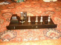
I finally got sorted with my daughters digital camera (added Ubuntu for handling the camera - couldn't as yet get Suse to recognise the USB card reader I have  ).
).
So heres a picture for your delectation.
Both of my headphones are relatively low impedance(10ohms and 32ohms) but I noticed that the higher of the two sounded slightly better with the lower one also plugged in. So I took your advise and added a 47R resistor over the high impedance output. Things seem more consistent now and it should cope better when I finally get some decent 'phones.
Shoog
).So heres a picture for your delectation.
One trick I've heard of is just to buid a normal OP stage, including transformer to match the tube to 8 ohm, and to connect an 8 ohm 'dummy load' resistor across the output. You then connect the phones across the dummy load. (It's done like that to avoid having to find a rare (and rather expensive) headphone tranny.)
Both of my headphones are relatively low impedance(10ohms and 32ohms) but I noticed that the higher of the two sounded slightly better with the lower one also plugged in. So I took your advise and added a 47R resistor over the high impedance output. Things seem more consistent now and it should cope better when I finally get some decent 'phones.
Shoog
Attachments
- Status
- This old topic is closed. If you want to reopen this topic, contact a moderator using the "Report Post" button.
- Home
- Amplifiers
- Headphone Systems
- Just finished a new PP headphone amp - and it works !!