2.1 Active Crossover
Hi all,
I decided to build my own crossover starting from the Active Filter Four project by Jens Rasmussen and Bob Ellis. This is my first project of this kind so please excuse me if I ask you stupid questions some time.
One PCB should accommodate two channels (stereo) and one sub-woofer common for both channels.
My first dilemma:
Do I need two LP filters and combine the signal before the output buffer or one LP filter can do both channels?
Here are some details about the OP-AMPs I intend to use:
- OPA1644 (14SOIC) for all the filter stages/sections. I will keep the original design with the selection jumpers between the 2nd order filters, just to have an idea about the differences between a 2nd order and a 4th order filter. I choose this OP-Amp because I may use only one to cover both 2nd order sections of a filter.
- OPA1602/2134 (8SOIC) for the input/output buffers. If you guys can recommend me one of them it will be nice, or I can try both to see the differences if any. I will use PCB adapters between 8SOIC and 8DIP.
Thanks,
Adrian
Last edited:
you can sum the two channels to give a mono channel.
You can then filter that mono channel to give a low bass only channel for a 2.1 system.
There is a filter that allows summing at it's input. Use an MFB low pass filter, Add one extra input resistor for each extra channel you want to sum. Yes one opamp does summing and 2pole filtering on one tiny PCB space. The MFB filter is inverting topology. The output is thus 180degrees out of phase with the normal channels. Swap the speaker leads if you need to get that channel back into phaseat the crossover frequency.
If you want/need more poles to the low pass filter just add on another S&K stage.
Power input connectors
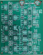
I've been using these crossover boards for years and have always wondered about the power input geometry. There are three large holes in the PCB, two at the edge are voltage in and the one behind is ground. Surely these must have been designed for some sort of connector but I've not been able to find anything that fits. I just soldered wires to the holes which works OK but I really think something else was intended here. Anyone have any ideas? See the attached picture.
Thanks Much
Attachments

- Status
- This old topic is closed. If you want to reopen this topic, contact a moderator using the "Report Post" button.
- Home
- Group Buys
- Active filter board GB