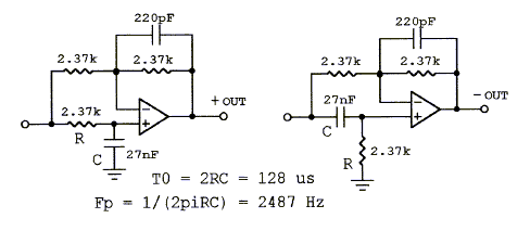
Yes, the Linkwitz transform section can be used for dipole eq. You'd jumper a few parts to convert its biquad to a twin-T but you wouldn't have to hang parts in the air. The topologies are so similar I missed the difference at first.
However, Linkwitz seems to prefer to use a shelving low pass (available in the input stage) and a notch filter (also on this board) for greater accuracy. With a notch you can more effectively kill that peak just before the dipole rolloff. See the Linkwitz filter page for more information (link earlier today in this thread).
However, Linkwitz seems to prefer to use a shelving low pass (available in the input stage) and a notch filter (also on this board) for greater accuracy. With a notch you can more effectively kill that peak just before the dipole rolloff. See the Linkwitz filter page for more information (link earlier today in this thread).
However, Linkwitz seems to prefer to use a shelving low pass (available in the input stage) and a notch filter (also on this board) for greater accuracy.
OK Bob, it's sound good so far!
I've looked at the SL circuits and that's the sort of thing that I want to achieve!
This thread is moving so fast. Would you believe that I have a new TV here today and I haven't had the chance to watch it yet!
 (Not that there is anything on there half as entertaining as diyAudio!)
 Nuuk - note the changes to my last post while you were posting. LT isn't quite what you want, but with a couple of jumpers you're there.
I am using a monitor I bought to strip for a DIY projector, so I know how you feel about new toys. I'm getting used to having two monitors on my desk. Projector may have to wait.
Edit: Good, you saw the change. You mean you've never made some mods to a board that didn't quite fit and ended up air-wiring a bit of the circuit?
Huh...go figure...
Just as I was getting back to this thread to say that maybe bandpass boards weren't such a bad idea after all (it looks like it could reduce # of opamps since you don't need multiple output buffers), Jens has gone and adopted my suggestion.
No room for indecision on this forum, I guess...
Either way, they still sound like a great idea, and a big to Jens and Bob for doing this, and another to Jens for doing it in Eagle Lite to make it accessible to everyone. (Sort of the GPL of PCB design.)
Can't wait to see a preliminary schematic...I understand pictures far better than words...
--Greg
Just as I was getting back to this thread to say that maybe bandpass boards weren't such a bad idea after all (it looks like it could reduce # of opamps since you don't need multiple output buffers), Jens has gone and adopted my suggestion.
No room for indecision on this forum, I guess...
Either way, they still sound like a great idea, and a big
to Jens and Bob for doing this, and another to Jens for doing it in Eagle Lite to make it accessible to everyone. (Sort of the GPL of PCB design.)Can't wait to see a preliminary schematic...I understand pictures far better than words...
--Greg
Nuuk - note the changes to my last post while you were posting. LT isn't quite what you want, but with a couple of jumpers you're there.
Yes, so I could use LT for my dipole woofers but it is better to use the other topology that you described in the second part of your post.
Two monitors! I have enough trouble keeping up with one!
YepSteen - are you paying attention?
Thanks for watching me, NuuK Well, I guess I have a lot of reading to do to understand this matter I am quite confident that I will in the end For now its just plain "wolapyk"
half of it
Steen
BobEllis said:Yes, the Linkwitz transform section can be used for dipole eq. You'd jumper a few parts to convert its biquad to a twin-T but you wouldn't have to hang parts in the air. The topologies are so similar I missed the difference at first.
However, Linkwitz seems to prefer to use a shelving low pass (available in the input stage) and a notch filter (also on this board) for greater accuracy. With a notch you can more effectively kill that peak just before the dipole rolloff. See the Linkwitz filter page for more information (link earlier today in this thread).
Could the spreadsheet be updated to include dipole EQ calculations?
Thanks a bunch.
This thread is moving so fast. Would you believe that I have a new TV here today and I haven't had the chance to watch it yet! (Not that there is anything on there half as entertaining as diyAudio!)
I am obliged to make a public apology to the BBC!
 The Folk Brittania concert on BBC4 is giving me goose bumps!
Is that concert on the internet broadcast?The Folk Brittania concert on BBC4 is giving me goose bumps!
I just love it, when music calls for goosebumps
Steen
For the rest of the picture thinkers out there, Here is a block diagram and some more words:
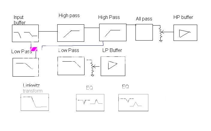
The input buffer includes a low pass filter to limit the bandwidth. It also can be configured to provide baffle step compensation or dipole EQ when used with a notch filter.
The high pass and low pass sections are second order and can make up to 4th order electrical filters. You can jumper the appropriate parts to make the section first order should you require an odd order filter. They can also be daisy chained to make a bandpass filter.
The topology is Sallen Key equal value, so gain and Q can be adjusted independently of frequency. Just because it is called equal doesn't mean that the components must be equal value even within a section. The circuit is effectively the same as the MOX, so if you find your optimum filter with a MOX you can plug the values that you selected with MOX's jumpers into this board (MOX Medium?) I'll update the spreadsheet to include calculations for component values with this topology. The spreadsheet calculates unity gain Sallen Key component values. You could use these by jumpering the feedback resistor. If you're looking for a straight Linkwitz-Reilly XO, use Rod Elliot's calculator.
Also provided on the board are the following that can be jumpered into either high pass or low pass sections:
Attenuators for both high and low pass sections and output buffers (balanced if Jens can fit it)
A Linkwitz transform (biquad) section. This can be used for extending the response of a subwoofer or any other 12 db/octave shelving Low pass requirement. As mentioned earlier, it can be used as a twin-T with a few jumpers, which may be suitable for some dipole applications. It might be reconfigurable for a shelving high pass application, should you need that.
Two EQ sections. These are configurable as notch or peak filters. Useful for taming breakup modes, filling in dips in response, as part of a dipole EQ section or in making a Cauer-Elliptic filter in conjunction with the HP and LP sections.
An All-Pass section. This is useful for adjusting the phase of a driver (usually tweeter) to compensate for the difference in acoustic centers and the driver's own phase shift.
I'll take a look at updating the spreadsheet to add dipole EQ calculations, although if someone else would like to do it, that would be great.
JensRasmussen said:What all pass topology do you want?
Left or right?
\Jens
Jens,
If there is room, can you include 5mm and 10 mm spaced pads so we could do either? (Like the optional pin spacing for the emitter resistors on your Leach boards) If not, go with the left. So far I haven't needed more than that much delay.
Edit: as long as I am making a wish list, if space permits, pads for two caps in the feedback portion of the LP sections. that would make it easier to make LR filters since any C value could easily be doubled.
Thanks Jens.
Do we really need the buffers between stages of each section (IC4B, IC5B, etc.) how about just a 2 pin jumper between IC4a pin 1 and C5. Pin 1 would also connect to JP8 pin 3. then 2nd order would be leave the new jumper out and JP8 pins 2-3, fourth order install new jumper wire and JP8 pins 1-2.
Getting rid of the interstage buffers would free up 2 dual op amps. Eliminate one and make an inverting output buffer?
If you think we must have those buffers, shouldn't the input connect to the output of the filter rather than the opamp negative input?
Out of curiosity, what have you used the buffered output (IC3B) for? As I typed I thought of using it for triggering a signal activated switch.
Bob
Bob,
The problem with setting the Q via the gain is the fact that you move the corner freq of your filter (from the 0dB situation). To adjust back to the original calculated value, the signal must be devided by the same as the gain in the filter section. This devided signal is already present at the inverting input of the filter opamp. All we need is to buffer it (to ensure that the gain of the filter is not changed)
I hope you understand what I try to say, if not try looking at the active filter one page, I have gone through the S&K filter and presented several setups of the filter.
\Jens
OK - I see the need for the buffers. Forgot about that part.
Looks great to me now.
BTW, your documentation for filters one and two was more helpful to my understanding filters than the usual recommendation, Don Lancaster's "Active Filter cookbook". thanks for publishing them.
Looks great to me now.
BTW, your documentation for filters one and two was more helpful to my understanding filters than the usual recommendation, Don Lancaster's "Active Filter cookbook". thanks for publishing them.
OK, so what can you do with these things?
With one board:
Single ended or balanced input
High frequency low pass (limits RFI)
TWO WAY CROSSOVER 1st - 4th order electrical or Cauer-Elliptic (gets a steep ~8th order initial rolloff but bounces back to 4th order but staying more than 50 dB down. Group delay is similar to 4th order throughout. Useful for pushing the low end limits of a tweeter)
If not using C-E, then two EQ sections are available for HF breakup modes or response dips.
Phase correction (delay) for either driver.
Baffle step compensation
Dipole eq - use BSC and Linkwitz transform as Twin-T for 12 db
MAIN TO SUBWOOFER CROSSOVER Stereo or mono subs, same orders as two way. Asymmetric slopes possible. Linkwitz transform available. EQ for room modes. Phase correction for sub to main speakers (for stereo subs in close proximity to mains)
BANDPASS FILTER
6th order bass reflex with high pass filter (1st -4th order)
THREE WAY (including 2 way + subwoofer)
requires two boards per channel
All of the "accessories" doubled, now 4 notches, 2 allpass, 2 6db shelving low pass, 2 biquad (Linkwitz transform)
A four way would require three boards per channel.
- Status
- This old topic is closed. If you want to reopen this topic, contact a moderator using the "Report Post" button.
- Home
- Group Buys
- Active filter board GB