GB2/Waiting List
Kokanee - 2 PCB + 12 transistors
baswamin - 2 PCB + 12 transistors
asanden - 2 PCB + 12 transistors
simon dart - 4 PCB + 24 transistors
BRN - 2 PCB + 12 transistors
Myint -2 pcb + 12 transistors
Others who are interested, please update the above list.
Thanks
GB2/Waiting List
Kokanee - 2 PCB + 12 transistors
baswamin - 2 PCB + 12 transistors
asanden - 2 PCB + 12 transistors
simon dart - 4 PCB + 24 transistors
BRN - 2 PCB + 12 transistors
Myint -2 pcb + 12 transistors
Johnny Canuck - 1 pcb + 6 transistors
Others who are interested, please update the above list.
Kokanee - 2 PCB + 12 transistors
baswamin - 2 PCB + 12 transistors
asanden - 2 PCB + 12 transistors
simon dart - 4 PCB + 24 transistors
BRN - 2 PCB + 12 transistors
Myint -2 pcb + 12 transistors
Johnny Canuck - 1 pcb + 6 transistors
Others who are interested, please update the above list.
A quick question if I may. Studying the boards in my hands against the images on the pdf and repeated in this thread. I noticed my boards are a mirror of the photos. Then I see on thr images v1.0R. I have v1.0L (×5). Should we have L and R boards?
Thanks
Edit.....dang.....post 1 states L and R boards.
Thanks
Edit.....dang.....post 1 states L and R boards.
Last edited:
Wow, I thought the PCBs were all the same. I was not aware there were different PCBs. I just thought that you get 5 PCB 2 for left 2 for right and one for test! I did only a quick inspection after receiving them (they all came in one bundle not separated) and they all look the same to me, not being aware that there are different versions.
So what is the difference between boards except being inverted?
So what is the difference between boards except being inverted?
The boards are identical in circuitry terms.
So you do NOT have to have R&L versions.
They are only more important when you build them as a pack in balanced mode.
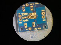
A Simple Discrete Current-Mirror IV Converter, à la AD844
I would not worry too much about it.
Patrick
So you do NOT have to have R&L versions.
They are only more important when you build them as a pack in balanced mode.
A Simple Discrete Current-Mirror IV Converter, à la AD844
I would not worry too much about it.
Patrick
John...I believe not but there appears to be a 2nd list forming a few posts back. Whether Ripster will go thru with this I cant say.
I don't know if this is the place to talk about building tjses things but here I go anyway...please advise if there is a better thread.
I am creating 4 rails, so 2 pos and 2 neg but using 4 times LT3042, so obviously each will have its own winding and rectifier.
Regarding transformers that I wish to order, I though about using small 'blue' encapsulated trafos. Maybe 6va so 3va per regulator. Is that enough or should I be upping the power rating.?
Regards
Jim
Edit....sorry I forgot about the 'other ' thread discussing this design. Shall ask there
Last edited:
Someone asked about a component pad in series with the input.
This is for a 0603 0R (jumper) resistor if you are using 1mA DAC current.
If you have more DAC current, you need to use multiple modules in parallel.
In that case, you should use a 1R resistor at that location.
So at least one person has started building.")
Patrick
This is for a 0603 0R (jumper) resistor if you are using 1mA DAC current.
If you have more DAC current, you need to use multiple modules in parallel.
In that case, you should use a 1R resistor at that location.
So at least one person has started building.
Patrick
Yup, that was me, guilty as charged. Thanks for the clarification of this resistor/jumper pad Patrick
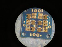
I finally got a chance to solder up a pair of boards, neat little buggers! Next step will be fine tuning with the trim resistors.
I finally got a chance to solder up a pair of boards, neat little buggers! Next step will be fine tuning with the trim resistors.
Attachments
- Home
- Group Buys
- GB: A Simple Discrete Current-Mirror IV Converter, à la AD844