Yeah, absolutely. Most chips are epoxied in their package.There is no other production-worthy method to attach a silicon substrate onto a carrier.
Which is why most semiconductor substrates are glued with silver epoxy.
This is also why even a TO247 device has such high Rthjc.
We can´t with most of our chips. We must epoxy the naked dies obviously.
The epoxy-"bed" is usually <<50µm. The dies are ~100µm high.
OK, back to topic.
(Just thought I´d mention it as some might have an arctic silver at home but not a proper solder gun.)
Epotek H20e has a thermal conductivity of 3.2W/mK.
SnAg solder has a thermal conductivity of 78W/mK.
https://www.epotek.com/docs/en/Datasheet/H20E-PFC.pdf
Thermal Conductivity of Solders | Electronics Cooling
Assuming the LU1014 is used in a power amp with 1.2A bias.
After cascoding, it will see a Vds of ~3V, or 3.6W.
It has a thermal pad approximately 6x7mm, or 42mm2.
Further, assuming a glue / solder thickness of 0.2mm.
From the above, the temperature drop across the Epotek comes to 5.4°C.
That of SnAg solder comes to 0.22°C.
I know which one I would use.
Cheers,
Patrick
H20E has a fracture toughness of about 0 once it's aged. I'd never use it where even the mechanical stress of soldered wires is applied.
")
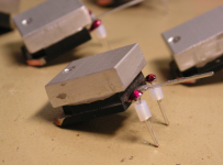
Our solution for heat sink mounting.
100W soldering iron minimum.
Patrick
.
Would doing something like this help much?
Attachments
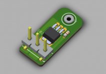
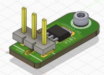
JPS64 is developing an adapter aluminum PCB to mount the LU1014D on to convert it to a TO-247 footprint. Also adding a gate snubber on board. The LU1014D is soldered in place using solder paste and hot plate/hot air and it will use the thermally conductive aluminum PCB as the thermal spreader to the heatsink. Aluminum PCBs are often used to mount high power LEDs to allow them to have heat conduction to a heatsink mounted to the bottom side of the PCB.
This configuration is for underhung mounting.

This configuration is for underhung mounting.
Attachments
Last edited:
The maximum packing density of vias in a normal PCB is 0.3mm dia on 0.6mm pitch.
That means 110 holes under the LU1014 footprint.
Normal plating thickness is ~20µm.
Copper thermal conductivity is 385W/mK.
Assuming the LU1014 sees 3V 1.2A, as already mentioned above; i.e. 3.6W.
Further assume PCB thickness of 1.2mm
The temperature drop just cross the PCB alone is 5.4°C.
Of course things will be much better if you use a ceramic or aluminium PCB.
As people do in professional boards for high-power (>3W) LEDs.
And we have not even discuss that the FR4 substrate is not stiff enough for spreading the clamping pressure uniformaly over the footprint.
That is turn will affect the effectiveness of the thermaI interfacing medium below, whether grease or Kerafol.
Patrick

Well, materials bonded with H20E (assuming you consider their CTE´s) survive thermal shock- htol- htb- and other tests just fine, otherwise who would use such an epoxy.H20E has a fracture toughness of about 0 once it's aged.
Read publications abot the subject if you´re interested but don´t post singular values out of datasheet or wherever if you don´t know what they mean or if they are even remotely relevant. Obviously you lack the experience working with such polymers and are certainly not part of the semiconductor-industry.
In turn this epoxy would also survive the biggest left-handed donkey in DIY who would permanently pull on the wires soldered to a transistor. (which is pretty stupid construction and thing to do in the first place)
The aluminium PCB is a very nice and probably best solutions for this.
Low thermal mass and thus you can quickly solder the FET to it.
Soldering for too long can severely affect Rthjc as well because of the.., you guessed it, epoxy in the package that gets soft of course being heated past its glass temperature.
Copper spreader is thermally better.
Mounting LU1014D
One can strip the copper plate from any scrap TO220 device, such as 78xx.
10 minutes work. Costs nothing.
Patrick
Mounting LU1014D
One can strip the copper plate from any scrap TO220 device, such as 78xx.
10 minutes work. Costs nothing.
Patrick
We will post the full binaries for the LU1014D TO247 adapter board shortly for anyone willing to handle the GB. I just checked and PCB way will make IMS in small quantities no problem. Single layer 1.6mm is only $26 for 10. A panel of 100 is only $43. So one does not even need to do a GB, although that would be great if someone could organize this with the devices themselves as most folks only need 2. This thread seems like the appropriate place to do this in addition to the devices themselves. It certainly looks a lot better than any makeshift copper spreaders - which don’t give you the nice solid upright pins for attaching to a PCB in an underhung fashion. Also, the temperatures to reflow onto the aluminum PCB will limit possible damage to the epoxy of the device itself as pointed out by joensd.
Last edited:
> Maybe I should not be so nervous about soldering these rare devices. But I am.
It is simple if you get some practice first (with say a MJD44H11 or any DPAK device).
The trick is to heat up the copper on top of a large piece of aluminium to say 170°C in an oven.
Apply solder to the position where you want to have the LU1014.
While the solder is being kept molten by the soldering iron, put the LU1014 in place with a pair of tweezers.
Keep holding the LU1014 while removing iron and allow to cool.
Works like a treat. Practice makes perfect.
Cheers,
Patrick
Installation of the LU1014 on the IMS PCB would be very simple - get an aluminum skillet or old frypan, apply circa 150C solder paste to the pads, place the LU1014 on the pad and put the frypan on a hot plate and use IR thermometer to make sure temps don’t exceed 260C for 10 seconds. But with 150C solder paste, you won’t need to get anywhere close to 260C Have a towel soaked in water nearby to cool frypan once melt is achieved. If the part hits 150C under normal use the solder will come apart of course. But that would be indicative of a bigger problem of either too much current or not a good thermal contact.
You can also heat frypan up to 125C and apply hot air from SMT rework tool over the top and extra heat liquifies solder paste and parts float into correct placement. Then remove hot air and part is never exposed to high temps for more than needed to liquify solder. Cool pan with wet towel and fan air over the top to cool part quicker.
You can also heat frypan up to 125C and apply hot air from SMT rework tool over the top and extra heat liquifies solder paste and parts float into correct placement. Then remove hot air and part is never exposed to high temps for more than needed to liquify solder. Cool pan with wet towel and fan air over the top to cool part quicker.
Last edited:
We will post the full binaries for the LU1014D TO247 adapter board shortly for anyone willing to handle the GB. I just checked and PCB way will make IMS in small quantities no problem. Single layer 1.6mm is only $26 for 10. A panel of 100 is only $43. So one does not even need to do a GB, although that would be great if someone could organize this with the devices themselves as most folks only need 2. This thread seems like the appropriate place to do this in addition to the devices themselves. It certainly looks a lot better than any makeshift copper spreaders - which don’t give you the nice solid upright pins for attaching to a PCB in an underhung fashion. Also, the temperatures to reflow onto the aluminum PCB will limit possible damage to the epoxy of the device itself as pointed out by joensd.
I'm organizing the GB for the Lu1014D. We're using Papa's supply. Still sorting out a few details before I post a signup spreadsheet with costs. I hope to have those details next week.
I like the idea of offering the Lu1014 PCB. PM me and lets see if we can get the PCB design finalized/tested so that we might be able to line up the PCB with GB device shipping time. I know ZM has some thoughts on the PCB.
- Home
- Group Buys
- Lovoltech LU1014 Power Jfet Group Buy