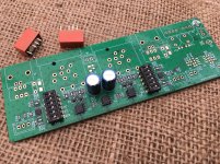
After spending several days of quality time listening just the LM4562 opamp in the BTSB v1.21p panel mount buffer, and I can say that it sounds excellent. The music is transparent and dynamic, clear. It does what it is supposed to do. Just don’t swap back and forth between the the OPA16xx’s! You might think that the grass is greener on the other side! ")
So just a note that if presented with a choice of not having a BTSB with OPA1656 or having one with LM4562, the latter is not a bad choice at all. It will not drive as low of an impedance load in SE mode as the OPA1656, which has a ridiculously high 100mA max current available. Basically almost a full headphone amp. Well, 4 paths of an OPA1656 (2 IC’s) in parallel can drive a 32ohm load to 1wrms with very low distortion, so that gives you a better idea of its capability.
So just a note that if presented with a choice of not having a BTSB with OPA1656 or having one with LM4562, the latter is not a bad choice at all. It will not drive as low of an impedance load in SE mode as the OPA1656, which has a ridiculously high 100mA max current available. Basically almost a full headphone amp. Well, 4 paths of an OPA1656 (2 IC’s) in parallel can drive a 32ohm load to 1wrms with very low distortion, so that gives you a better idea of its capability.
More SMD therapy
Right at the very end, one single resistor pinged off forever. R31 will be left unpopulated until next order. I also forgot to include D6/D7 to the last order.
xrk971 - what is J8 used for? sorry if i missed the info. I'll only be using the balanced output.
Right at the very end, one single resistor pinged off forever. R31 will be left unpopulated until next order. I also forgot to include D6/D7 to the last order.
xrk971 - what is J8 used for? sorry if i missed the info. I'll only be using the balanced output.
Attachments
Nice work Passive420! J8 is a protective earth ground with ground loop breaker for connection to chassis ground to reduce RF noise pickup, it it is a problem. D6 and D7 are there to protect the MOSFETs driving the relays from the solenoid back EMF. You can use any diode like 1N4148 or 1N400x axial with bent leads there in a pinch.
xrk971 - another question my friend.
To test the SE input to BAL output I will simply hardwire to the board from panel RCA's (I'm a bit lazy getting the PCB RCA's from Audiophonics due to shipping costs)
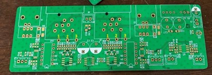
Below is a pic of the PCB with holes numbered, Is it correct to fire the RCA signal wire to hole #1? I want to bypass the relays initially.
edit: sorry just probing around, inputs are on R1/R2 & R3/R4, schematic page on page 1 shows R1 & R3 look good.
To test the SE input to BAL output I will simply hardwire to the board from panel RCA's (I'm a bit lazy getting the PCB RCA's from Audiophonics due to shipping costs)
Below is a pic of the PCB with holes numbered, Is it correct to fire the RCA signal wire to hole #1? I want to bypass the relays initially.
edit: sorry just probing around, inputs are on R1/R2 & R3/R4, schematic page on page 1 shows R1 & R3 look good.
Attachments
Last edited:
Yes, you can use flying leads for the RCA’s - but you must use the specified Neutrik 11pin XLR as it has plug sensing switches which activate the RCA’s. It would be a tricky routing correction job to keep the relays but to simulate the XLR plug sensing circuit.
If you did not want to mess with the XLRs and RCAs getting the non-panel mount SMT one might have been better.
If you did not want to mess with the XLRs and RCAs getting the non-panel mount SMT one might have been better.
Just made a horrible discovery - Audiophonics have increased the minimum order amount to UK to 160 euro. This is very recent so I missed the boat. Not a massive problem for the RCA's but it's nice to fill the PCB.
If any French members read this and can help send me a pair of ELECAUDIO ER-106 Inlet RCA, I will be eternally grateful, I will obviously pall all costs.
ELECAUDIO ER-106 Inlet RCA for IC Gold Plated (Pair) - Audiophonics
If any French members read this and can help send me a pair of ELECAUDIO ER-106 Inlet RCA, I will be eternally grateful, I will obviously pall all costs.
ELECAUDIO ER-106 Inlet RCA for IC Gold Plated (Pair) - Audiophonics
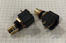
I’m trying to get RCA jacks that fit in the same footprint as the Elecaudio. They are not made by Elecaudio but are very similar. I’ll see if I can sell them in my shop. I know these are hard to find and expensive when you do find them. Will hopefully have them soon and offer them for $15/pair. Is this something of interest to folks?

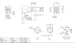
Drawing (note that the vertical distance from the PCB surface to RCA axis is 1mm taller than the Elecaudio jack, otherwise the dimensions are compatible):
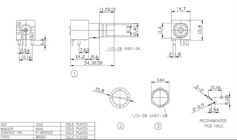
Drawing (note that the vertical distance from the PCB surface to RCA axis is 1mm taller than the Elecaudio jack, otherwise the dimensions are compatible):
Attachments
Last edited:
RCA’s now in my shop as well as an option with the BTSB Panel Mount.
PCB mounted 90deg RCA jacks | Etsy
PCB mounted 90deg RCA jacks | Etsy
Troubleshooting
Hello everyone - just assembled one THD board and have some noise problems. Hopefully someone can point me in the right direction. Here is the situation:
BTSB powered by Mark Johnson's VRDN at +/- 15V. I have used the PS previously with my DAC so I know it works.
CD player output to BTSB over SE (-ve and ground jumped at BTSB)
BTSB SE out to Class D commercial amp
Problem(s) include audible hum with no input and very distorted "spitty" noise on top of the music (both channels) on playback.
I have not grounded the BTSB - should I tie that to PS GND or chassis?
Thanks in advance for any help.
Best,
Mike
Hello everyone - just assembled one THD board and have some noise problems. Hopefully someone can point me in the right direction. Here is the situation:
BTSB powered by Mark Johnson's VRDN at +/- 15V. I have used the PS previously with my DAC so I know it works.....
Hi,
You didn’t install the BTSB onboard dc/dc converter psu and are powering it from an external VRDN, correct?
Can you post pictures of your setup?
Hi,
You didn’t install the BTSB onboard dc/dc converter psu and are powering it from an external VRDN, correct?
Can you post pictures of your setup?
Correct I went direct to the secondary side of the (missing) converter. I think I have it sorted. Tied board ground to chassis that stopped the hum. May have had a bad connection in the PSU. Now playing!
Mike
Great news!
I built a couple of the SMD versions and tried an external psu setup, similar to what your doing, based on TPS7A47xx/33xx regulators. I couldn’t tell a difference in sound compared to the BTSB’s built with the onboard dc converter. Always fun to experiment though.
I built a couple of the SMD versions and tried an external psu setup, similar to what your doing, based on TPS7A47xx/33xx regulators. I couldn’t tell a difference in sound compared to the BTSB’s built with the onboard dc converter. Always fun to experiment though.
Yeah I wasn’t expecting any audible difference just trying to avoid the need for another power supply.
Here’s a question that I’m wrestling with: I want to assemble an active preamp around a Muses volume and these buffers. I plan to buffer the output but is there any benefit to buffering inputs also?
Best,
Mike
Here’s a question that I’m wrestling with: I want to assemble an active preamp around a Muses volume and these buffers. I plan to buffer the output but is there any benefit to buffering inputs also?
Best,
Mike
Correct I went direct to the secondary side of the (missing) converter. I think I have it sorted. Tied board ground to chassis that stopped the hum. May have had a bad connection in the PSU. Now playing!
Mike
Hi Mike,
Glad you got that sorted out. Note that there is analog 0v clean ground that should connect to the 0v of your PSU GND. The chassis ground should connect to one of the mounting bolt pads that has a 10ohm (and 100nF) ground loop breaker. That will help to reduce ground loops, if any.
The on board PSU costs only $6 and provides 5kV of galvanic isolation between the 12v input and BTSB preamp. I have measured the noise floor as -135dB so it’s very quiet.
- Home
- Group Buys
- BTSB Buffer - SE/Bal to SE/Bal Buffer GB