Regarding the Fischer heatsinks: Just need to know someone in Germany. ")
The ACP+ as designed is really for driving headphones. So the bias current is a rather high 150mA. It runs too hot with these tiny heatsinks.
dBel84 did the following changes to drop the current and it runs at 40C.
R111 = 3K
R115 = 3R2
R117 = 10R
I seem to recall these settings were for about 70mA bias current. Plenty as a preamp and even for higher impedance headphones.
Last edited:
GB update:
Thank you Mshipman!
MShipmanPE / SMT Prepopulated / 2 boards/ USA *Pre-Order Placed*
Carl_Huff / bare PCB / 2 boards / USA
mnichols30030 / bare PCB / 2 boards/ USA
Thompsontechs / bare PCB / 2 boards / USA God Bless it in these trying times!
Aljordan / SMT Prepopulated / 2 boards / USA *Pre-order Placed*
Pwagner / SMT Prepopulated (if enough interest) / 2 boards / USA
jwjarch / bare PCB / 2 boards / USA * Order Placed*
meanie / SMT Prepopulated / 2 boards / SGP
diy40 / SMT Prepopulated / 2 boards / USA
Itsmee / SMT Prepopulated / 2 boards / UK *Pre-order Placed*
Bones13 / SMT Prepopulated / 2 boards / USA *Pre-order Placed*
Afoor / bare PCB / 2 boards / USA *order placed*
Thank you Mshipman!
GB status update:
MShipmanPE / SMT Prepopulated / 2 boards/ USA *Pre-Order Placed*
Carl_Huff / bare PCB / 2 boards / USA
mnichols30030 / bare PCB / 2 boards/ USA
Thompsontechs / bare PCB / 2 boards / USA God Bless it in these trying times!
Aljordan / SMT Prepopulated / 2 boards / USA *Pre-order Placed*
Pwagner / SMT Prepopulated (if enough interest) / 2 boards / USA *Pre-Order Placed*
jwjarch / bare PCB / 2 boards / USA * Order Placed*
meanie / SMT Prepopulated / 2 boards / SGP
diy40 / SMT Prepopulated / 2 boards / USA
Itsmee / SMT Prepopulated / 2 boards / UK *Pre-order Placed*
Bones13 / SMT Prepopulated / 2 boards / USA *Pre-order Placed*
Afoor / bare PCB / 2 boards / USA *order placed*
Hi Folks,
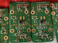
We are going to test out the lower bias current configuration before committing to get the BOM for all the prepopulated SMT boards. So this will take another week or so then we will be in production. I have the PCBs and solder stencil already. Just need to order the MELF resistors and the opto and BJT. We are moving forward with this. Please place your pre-order soon if you are interested in the prepop'd board as the window is closing soon.
Thanks,
X
Hi Folks,
We have just tested the ACP+ with the new reduced bias current settings. The current is now 75mA vs 125mA and temps are down to 56C at the heatsinks. Even at 75mA you can drive moderate impedance headphones quite nicely. As a preamp though, it can drive any input of an amp. We are noticing that it will take some fiddling with various values of trim resistors to set the bias current of the JFETs precisely. There are extra large pads there so you can add in parallel, values that can fine tune the bias.
We have just tested the ACP+ with the new reduced bias current settings. The current is now 75mA vs 125mA and temps are down to 56C at the heatsinks. Even at 75mA you can drive moderate impedance headphones quite nicely. As a preamp though, it can drive any input of an amp. We are noticing that it will take some fiddling with various values of trim resistors to set the bias current of the JFETs precisely. There are extra large pads there so you can add in parallel, values that can fine tune the bias.
Thanks for the update!
I know everyone else here knows how, but, could you outline the bias setting? Where to measure, and the desired value. Is it twitchy enough that I should dial in with a trimmer resistor, and order a specific resistor value for each board? Or would a few smaller values (5R, 10R, etc) handle the range to add?
Ok, looked at the page on FirstWatt.com - 10 milliamperes across the R104/R105 parallel resistors.
If perfection is wanted, I would think leaving off the 200R, preset the trimmer pot to 200R, the adjust for desired bias, measure pot, and then order as close a resistor as possible.
Or is that too much work for obtaining a good result?
Last edited:
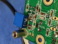
R105 pads were originally spec’ed for a mini-MELF resistor holder. It’s a socket that you can swap resistors in/out very easily. But the problem is I can’t get the holder in the US. SMD component holder for Mini-MELF | Burklin Elektronik
With a bit of creativity, your temporary 200R Bourns type trimpot solution soldered to the larger R105 pads will work. Adjust the trimpot to 125R before installing. The trimpot will be used to calculate the resistor that eventually will be soldered to R104 location once the trimpot is removed. Using this method, just one MELF resistor is installed instead of parallels.
I’ve gone as low as 33R to get the recommended 10mA
That sounds like a plan: wires to R105 to attach trimpot, and to measure current from. Then order a specific resistor for each board. How long to warm up the board for measurements? I’m assuming I could use a bench PS for biasing? (+24 / Ground) without having to install the boards for biasing.
TYVM for the comments, and confirmation.
TYVM for the comments, and confirmation.
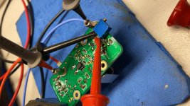
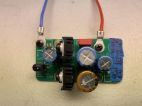
I built an ACP+ board today and tried the “trimpot mod” to dial in the 10mA across R104/105. I soldered the trimpot legs directly to the R105 pads, initial setting was 125R. Then tapped power directly from the Yarra psu and fired up the ACP+. With 125R bias was 6.8mA, turning down the trimpot and checking bias along the way, finally settled at 60R.
.612v/60r = 10.2mA Good Enough!
I didn’t have a ‘close to’ 60R MELF resistor, so I left the pot soldered to the board and installed the ACP+ in my Yarra. Singing away beautifully with a bit of traditional Christmas music to get into the season.
Note: There is no need to parallel resistors at R104/R105 if you get the exact value needed via the trimpot. Just install the resistor at R104 and remove the trimpot. R105 remains unpopulated.
Attachments
Last edited:
I built an ACP+ board today and tried the “trimpot mod” to dial in the 10mA across R104/105. I soldered the trimpot legs directly to the R105 pads, initial setting was 125R. Then tapped power directly from the Yarra psu and fired up the ACP+. With 125R bias was 6.8mA, turning down the trimpot and checking bias along the way, finally settled at 60R.
.612v/60r = 10.2mA Good Enough!
I didn’t have a ‘close to’ 60R MELF resistor, so I left the pot soldered to the board and installed the ACP+ in my Yarra. Singing away beautifully with a bit of traditional Christmas music to get into the season.
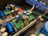
Looking good! Proof of concept.
Hi Bones13,
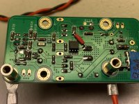
Remove your ACP+ from the Yarra and make two power cables with a crimp ring terminal on either end. (Or alligator clips on both ends) Take power directly from your Yarra motherboard outside the chassis so you can work on your daughter board in the open. You will have the trim pot connected so you can easily adjust and test with your DMM for correct voltage to get the 10mA. If done this way, you don’t have to estimate the bias based on a different power source.
Remove your ACP+ from the Yarra and make two power cables with a crimp ring terminal on either end. (Or alligator clips on both ends) Take power directly from your Yarra motherboard outside the chassis so you can work on your daughter board in the open. You will have the trim pot connected so you can easily adjust and test with your DMM for correct voltage to get the 10mA. If done this way, you don’t have to estimate the bias based on a different power source.
Attachments
- Home
- Group Buys
- ACP+ Preamp/HPA for Yarra Preamp