Francois,
Active rectifier or synchronous rectifier is the right name for "Ideal bridge/rectifier". It is not a new concept and it was used since 50's.
Even electric trains make use of this concept with synchronous motor rectification.
Some documentation was presented on the opening of the first group buy. Ideal bridge rectifier GB
Diodes, silicon or vacuum, act as dynamic resistance with important voltage drop variation related to the operating point. Over a normal silicon diode you have voltage variation between 0.5V up to 1,7V with forward current and over a diode tube between few volts and ten's of volts.
In a class AB amplifier, this affect dynamics and amplifier capability to drive low impedance speakers.
This is not the case with a class A amplifier where current is constant and therefore Vf variation is inexistent.
An “Ideal diode” or Active Rectifier is based on a controlled ultra low Rdson MOSFET, where series resistance is Rdson.
Rdson - is the effective drain to source resistance of the MOSFET transistor at a given Vgs - grid source voltage and Vds - drain source voltage.
Rdson is not a constant parameter, but over a threshold Vgs, the variation of this is very low with forward current, in comparison with a diode.
Modern MOSFET transistors exhibit under 1miliohm Rdson. This translate in 0,1W dissipated power at 10A.
At 10A a Schottky diode will dissipate at least 10W and a normal diode over 15W.
At high frequency and high voltage there are two completely separate phenomenon going on, one is diode switching noise, the other one is diode ringing. There is no relationship to each other and are caused by very different things. The noise that results is also very different.
Both are addressed by using Active Rectification with low Rdson MOSFET's.
Advantages of Active Rectification at low voltage is obvious, low dissipated power, higher output voltage, excellent efficiency and stable operation where high current variation occur. Also there will be no switching noise or ringing.
At high voltage silicone diode noise is even more important. In some cases this is the main source of noise in your tube or solid state pre/amplifier. Using Active Rectification may improve noise and in some cases dynamics.
To conclude.
IMHO, Active Rectification using "Ideal diode/bridge" is a modern approach that reduce dissipated power and noise in any application.
As disadvantage I would mention, cost. But sometimes, heatsinks or complex LC. CRC, RC filters and snubbers cost will be over "Ideal Bridge".
Regards,
Tibi
Last edited by a moderator:
Tibi, something occured to me with regards to the HV rectifier board.
I suppose you have only tested it with cap input supplies. If choke input is used, the 450v limit of the LR8 is extremely easy to reach at relatively low DC voltages.
Even with external 15v it is hard to say how safe the boards will be if choke input is used. Depending on choke/cap parameters 1000v spikes at the rectifier outputs are easy to reach upon power on with only 300v AC coming from the transformer.
If anyone intends using these with choke input supplies a soft start circuit at the boards output appears a must.
All this only imho of course.
analog_sa,
The bridge was tested at the input o 2 different SMPS, one 1,2KW and one 400W. Both have input choke filters. Regulators will deal just fine with spikes generated at power on/off.
My amplifier have the 1,2KW SMPS and Saligny HV bridge will stay there. There is no way to come back to a normal or Schottky bridge.
The HVHV limitations have been presented in the first thread.
With on board regulators, I consider safe his use up to 300Vac This mean you will get at the output 425V.
Over this voltage the bridge may be used, with external un/regulated 15V power supply, up to 400Vac, respectively at 565Vdc output.
Those limitations are imposed by board internal regulators - 450V - and by the mosfet type used - 650V.
Regards,
Tibi
Attachments
One very important observation.
In order to work properly, Saligny LC, Stantard and HVHF need output filter capacitors.
This bridges are self-powered. At very first start internal body MOSFET diodes are used as rectifiers. As soon output voltage reach threshold operation, MOSFET's are activated. In order for this to happen, an output capacitor filter is needed.
Saligny HC have a different mode of operation and may be used without output capacitors.
Regards,
Tibi
Thank you!
Not sure if the smps choke input is directly comparable to what is typically used with valves. Do you have any data on the chokes? Are they above critical inductance?
Otoh, the spikes are not nearly as high as i feared as these boards have output caps, perhaps around 1uF which makes true choke input impossible.
Ha, ha. I wrote this at the same time as your post.
In tube rectifiers, usually large chokes, are used after rectifier in CLC filters.
Saligny HVHF have two fast diodes that will protect board regulators in case any spike output voltage will exceed input.
Except SMPS, if you know any specific application where choke is before rectifier, please let me know.
Regards,
Tibi
Saligny HVHF have two fast diodes that will protect board regulators in case any spike output voltage will exceed input.
Except SMPS, if you know any specific application where choke is before rectifier, please let me know.
Regards,
Tibi
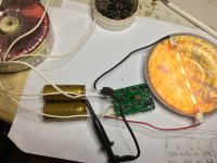
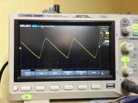
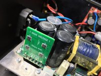
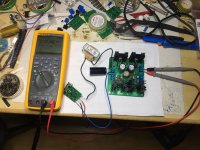
I can do better than a simulation.")
Saligny HVHF directly connected to 220V mains, a huge 5H choke a 220uF/450V cap and HMN regulator.
Seems that I have to adjust some resistors on that HMN regulator.
Regards,
Tibi
Saligny HVHF directly connected to 220V mains, a huge 5H choke a 220uF/450V cap and HMN regulator.
Seems that I have to adjust some resistors on that HMN regulator.
Regards,
Tibi
Attachments
Last edited by a moderator:
analog_sa,
The bridge was tested at the input o 2 different SMPS, one 1,2KW and one 400W. Both have input choke filters. Regulators will deal just fine with spikes generated at power on/off.
My amplifier have the 1,2KW SMPS and Saligny HV bridge will stay there. There is no way to come back to a normal or Schottky bridge.
The HVHV limitations have been presented in the first thread.
With on board regulators, I consider safe his use up to 300Vac This mean you will get at the output 425V.
Over this voltage the bridge may be used, with external un/regulated 15V power supply, up to 400Vac, respectively at 565Vdc output.
Those limitations are imposed by board internal regulators - 450V - and by the mosfet type used - 650V.
Regards,
Tibi
Hi,
Any chance this can be used with our local main supply to be 230Vac?
If so, i would like to buy some.
Thanks.
Saligny HVHF directly connected to 220V mains
It will be more convincing @320v AC and a series of on/offs, preferably automated as this is the only instance of risk. What is the choke dc resistance?
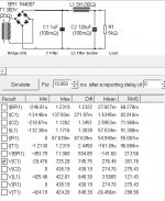
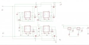
Looks like i shall be ordering a few boards with the explicit intention to find out the limits of safety with inductive inputs following the attached circuit. Transistor types are different from the indicated, only used those for the footprints.
Attachments

- Home
- Group Buys
- Ideal Bridge second GB