Hi audio members,
I am about to begin soldering the FH9HVX pcb. The H111 led is to be populated on the pcb as "anode to ground". Since I am a laymen when it comes to electronics, would this mean that the anode is soldered on the 0V side or the R111 side, when looking at the pcb. If the thick dark trace passing through H111 is a ground trace then the anode would be towards the 0V on the pcb. Correct?
Thanks for the help,
Myles
The anode is the longer lead and the cahode is the flat on the round LED. So long lead toward the pad that is connected to ground. Looking at the board with the inductor and MOSFETs at the top, the LED longer lead goes into the top pad closest to the 0v Faston pin. The flat faces down.
Hi X,
Mouser sent me a 0.022 uF 630VDC smd cap for part for C151 which will not work as C151 is a thru hole on the pcb. I have some Wima 0.022uF, 400VDC, thru hole metal film caps on hand which I can bend to fit in the C151 spot if OK for voltage. Let me know your thoughts on this. Thanks.
MM
Mouser sent me a 0.022 uF 630VDC smd cap for part for C151 which will not work as C151 is a thru hole on the pcb. I have some Wima 0.022uF, 400VDC, thru hole metal film caps on hand which I can bend to fit in the C151 spot if OK for voltage. Let me know your thoughts on this. Thanks.
MM
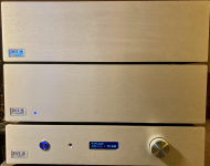
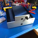
Finally!
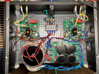
Just fired up my FH9HVX - everything looking good and playing music.
I need to tidy up the wiring before buttoning it up.
Before you ask - I deviated from my usual obsession with symmetrical chassis layouts, but I wanted to try Prasi's LT4320 CRC filter board and ran out of real estate in the 3U box. I could have mounted the amp boards on the heatsinks to make more room, but got impatient and did not feel like doing the extra hole tapping.")
Anyway - sounds great. Thanks to X, JPS64, and Vunce for a fun project!
Just fired up my FH9HVX - everything looking good and playing music.
I need to tidy up the wiring before buttoning it up.
Before you ask - I deviated from my usual obsession with symmetrical chassis layouts, but I wanted to try Prasi's LT4320 CRC filter board and ran out of real estate in the 3U box. I could have mounted the amp boards on the heatsinks to make more room, but got impatient and did not feel like doing the extra hole tapping.
Anyway - sounds great. Thanks to X, JPS64, and Vunce for a fun project!
Attachments
Hi Wtnh,
Wow! Very nice work - actually it is very neat and tidy as is. You are going all out with the Prasi premium CRC PSU with LT4320's - very good choice for this amp. Is that a standard 300mm deep Modushop 3U Dissipante chassis? You might consider a speaker DC protection board.
Happy listening!

Wow! Very nice work - actually it is very neat and tidy as is. You are going all out with the Prasi premium CRC PSU with LT4320's - very good choice for this amp. Is that a standard 300mm deep Modushop 3U Dissipante chassis? You might consider a speaker DC protection board.
Happy listening!
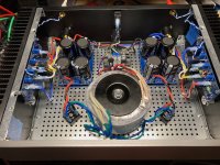
Yes - standard 300mm 3U Dissipante. Prasi's LT 4320 board worked perfectly. With an Antek 36 Volt 300 VA dual winding transformer, I get +/- 48 Volts. I used 4x 22,000 uFD 63 Volt caps. Obviously going this route drove the PSU price up a bit, but I was anxious to try it out.
I do notice a bit of downward bias drift as it warms up. This is because at idle the heatsinks are not even lukewarm. If I set it to 33mV cold, it will drop to about 28mV once it warms up. Of course, this is preferable to the opposite condition, which might lead to thermal runaway!
I am saving my pennies for SSR boards.
Last edited:
Your FH9HVX Looks sweet Wtnh!! Congratulations on a smooth power up. I wanted to use an LT4320 based rectifier also with Prasi’s PSU, but the trafo I’m using is center tapped. If I remember correctly, Bias is about 140mA. The sinks are barely warm!
PS: Your transformer is not centered
PS: Your transformer is not centered
Only a few hours so far with my "street speakers", but I can say it is very clean in the midrange and high end and has plenty of low-end "grunt". I would describe it as effortless since it has so much reserve power.
I am still tweaking bias. My workbench area is a bit chilly (65 F) so it takes about an hour of playing at moderate volumes to reach thermal equilibrium.
Still to do - button it up and do some full-power dummy load testing and distortion measurements.
I may get brave and try it with my Martin Logans - but I will probably wait until I can install SSRs. I may a-b it with my McCormack DNA (500 Watts), but I suspect it will hold its own.
So far I am very happy with the sound! I would recommend this amp to anyone wanting to build a quality A/B amp and I am very glad I chose it.
Glad to hear that the amp is sounding promising. Effortless is a good word to summarize it.
Your chassis heatsinks are probably oversized. I would not worry about it reaching equilibrium - it gets there eventually. You can also leave it on - but maybe wait until you have an SSR speaker protect to do that.
I am still tweaking bias. My workbench area is a bit chilly (65 F) so it takes about an hour of playing at moderate volumes to reach thermal equilibrium.
Your chassis heatsinks are probably oversized.
I would not worry about it reaching equilibrium - it gets there eventually. You can also leave it on - but maybe wait until you have an SSR speaker protect to do that.If you wish to play at 100w continuously, the thermal efficiency of Class AB is 67% so it would dissipate 33W. Assuming 55C max, 22C ambient or 33C rise allowable. That’s 33C/33W or 1C/W heatsink rating. Or 1Kelvin/W rating type heatsink.
Visually, the heatsink would need to be sized to be about 1/2 of what typical Class A amps of the 25W category. So imagine a 2U x300mm heatsink per channel is about the size you need.
Visually, the heatsink would need to be sized to be about 1/2 of what typical Class A amps of the 25W category. So imagine a 2U x300mm heatsink per channel is about the size you need.
That makes sense - my class A amp runs about 75 Watts per channel and the 300 mm 3U Dissipante heatsinks on it only get to about 125F. The FH9 would probably even work fine in a 2U chassis if you could squeeze the PSU and transformer in. I suppose a pair of low-profile SMPSs would do the trick, or maybe filter boards with horizontally mounted caps.
It looks like @dBel84 managed in a low-profile chassis.
Then, of course, there is always the griddle approach.
It looks like @dBel84 managed in a low-profile chassis.
Then, of course, there is always the griddle approach.
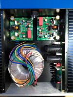
Bit of progress, what are your thoughts on the mosfet/heatsink location here? I know it's not ideal but wondered if it'll just run warm or be detrimental - I was going to look at it under a Fluke FLIR when assembled to confirm. Mounting is 2/3rds the way up a 2U x 2in x 12in radiator, but all the way to one end.
Attachments
- Home
- Group Buys
- FH9HVX - Budget Conscious 100w Class AB for Lean Times