Contemplating power supplies for my FH9HVX build and stumbled upon this boost board using 12v input. Seems like an interesting potential solution. Is it legit? Would it need heat sinking at the current draw from the FH9HVX? Curious to hear everyone's thoughts.
new version 1200W DC12V to DC+-52V Switching boost Power Supply board | eBay
new version 1200W DC12V to DC+-52V Switching boost Power Supply board | eBay
zman01,,
My base on the hs is only 6mm, so will drill thru and use nuts & bolts. Do you use a torque screwdriver for tightening down the transistors?
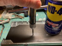
Here are a couple of photos I took during my build. The first shows tapping for the M3 MOSFET mounting bolts. I use WD-40 and tap slowly, backing out and cleaning the tap if too much resistance is felt. I would guess my taps ran about 5-6mm deep.
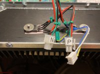
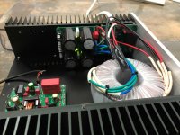
The second shot shows the MOSFETs mounted on the heatsink assembly. The Molex plugs on the flying leads were labeled so I did not mix them up. The MOSFETs are insulated from the heatsink with Keratherm insulators and mounted using fender washers and M3 hardware. The fender washers serve to distribute the pressure from the mounting bolts across the face of the MOSFETs, preventing stress fractures. I did not use a torque wrench but snugged them down slightly past finger-tight (maybe 1/2 turn). I included split lock washers on the M3 bolts to keep the bolts from loosening during thermal cycles.
You can also see the VBE multiplier transistor in the middle, which does not require insulation and has a smaller washer.
Attachments
Last edited:
That's a great point bullittstang. Good to weigh all the options since there aren't a ton of +/- 52v switching supplies out there. Looks like there are a few +/- 50v out there. I'll do a little more research on those.
Nice work wtnh. What size heatsink/chassis did you end up going with for your build?
Nice work wtnh. What size heatsink/chassis did you end up going with for your build?
Contemplating power supplies for my FH9HVX build and stumbled upon this boost board using 12v input. Seems like an interesting potential solution. Is it legit? Would it need heat sinking at the current draw from the FH9HVX? Curious to hear everyone's thoughts.
new version 1200W DC12V to DC+-52V Switching boost Power Supply board | eBay
Unless you plan on using large lead acid batteries to power your amp, or you are off the grid with solar or wind power, it doesn't make sense. I have used these boost modules to power a Class D amp - they are 90% efficient so it was semi practical to run on batteries for 6hrs and then trickle charge the battery the rest of the time.
You could get a 120vac to +/-55v 600w SMPS for $105. Check out Micro-Audio (Cresnet). They work very well and super quiet.
SMPS630-G – MicroAudio
They make auxiliary power for your preamp or MCU too.
Quick question I need help with. What is the black enclosure that encompasses V101 and V103 and why is it needed?. Is it heatshrink?
Thanks for the help,
MM
I think some people have used heat-shrink or zip ties to thermally couple the two transistors, which is good practice. This gives good thermal tracking. I did not bother since the amp seems to not need any DC offset adjustment. So far, my build has worked fine without bothering.
Last edited:
When you clamp on it with a zip tie or shrink tube it will be pretty flat - I try to pre-bend the legs to make the faces parallel and close to each other. Don't worry about it - it is a very minor effect as the two transistors are already very close together and should experience a similar temperature environment. No problems if they touch, you actually want them too - they are plastic bodies so no issue.
I would not think so.
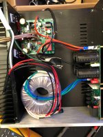
BTW - the reason I was not concerned with thermal coupling of the input pair is that this amp has unity gain at DC. In other words, any offset caused by a mismatch or lack of thermal tracking between the two transistors is multiplied by 1, nothing more. It is one of its advantages. That, plus my boards are mounted horizontally, so the transistors will be pretty close in temperature inside the enclosure and the junction temperature will be kept close by the PC traces and the emitter resistors.
BTW - the reason I was not concerned with thermal coupling of the input pair is that this amp has unity gain at DC. In other words, any offset caused by a mismatch or lack of thermal tracking between the two transistors is multiplied by 1, nothing more. It is one of its advantages. That, plus my boards are mounted horizontally, so the transistors will be pretty close in temperature inside the enclosure and the junction temperature will be kept close by the PC traces and the emitter resistors.
Last edited:
Hey all, need some help debugging the FH9 board I assembled. The All Cee's board is outputting +/- 50V as expected, however all of the bias pins are 0V potential to the 0V input. The red LED is not lighting, but I believe that may be backwards. Any specific areas to probe to localize the issue? (or am I just missing something, and it's set up incorrectly?)
Attachments
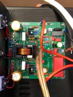
LED cathode needs to face away from ground pin next to it. That is the flat facing down with orientation of board with MOSFETs up on top. ( to the right in photo shown)
Your flying leads on MOSFETs look too thin. Should be at least 18ga quality stranded copper wire. Preferably silicone jacket high strand count to reduce mechanical strain.
Check bias across test point leads next to white KOA resistors.
What is voltage on each of the 3 pins of the the two MOSFETs relative to ground? Measure that.
- Home
- Group Buys
- FH9HVX - Budget Conscious 100w Class AB for Lean Times