It's possible that my request was the type "share a bill", please check again, I've refunded you and sent a new request.
Turion64 just paid correctly the new invoice and now I have a shipping address.
For me it goes straight to the billing statement once again. But what I do notice up above it is set to "Sending to a friend" and once I click on the "change" selection I can change it to the "Paying for an item or service" selection. But you do know there are fee's associated with that option on your behalf? I hope you've adjusted invoicing with the included fee's to the buyers?
Attachments

For me it goes straight to the billing statement once again. But what I do notice up above it is set to "Sending to a friend" and once I click on the "change" selection I can change it to the "Paying for an item or service" selection. But you do know there are fee's associated with that option on your behalf? I hope you've adjusted invoicing with the included fee's to the buyers?
Perfect, I'm happy you found the correct option.
")
Sending to a friend is a recent addition, all prices (boards, options and shipping) already includes PP fees.
Perfect, I'm happy you found the correct option.
Sending to a friend is a recent addition, all prices (boards, options and shipping) already includes PP fees.
Ok, I just wanted to make sure you included paypal fees since I know the other option doesn't include them, only fees associated with oversees/money conversion type transactions which would be on my behalf if so. Payment is sent, and you should have an address now.
Some PCB porn
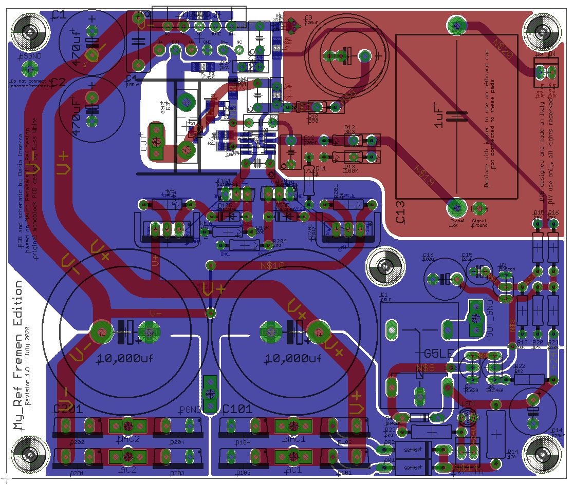
Still refining but so far:
Tom do you see something?
Changes so far from 1.72:
Still refining but so far:
Tom do you see something?
Changes so far from 1.72:
- C1, C2 13mm diameter, dropped 16mm support
- C4 moved to make place for R3
- Rearranged LM317 orientation to make place for R3
- R3 is TO-247 now to support manganin resistors
- R3 both orientation are supported and there is space for a Fischer FK 243 MI 247 O clip-on copper heatsink
- Dropped FE compensation, Evo A only
- C10 replaced with C33 negative feedback (other opamps support)
- C9 now support 18mm diameter caps (100V Cerafine for instance...)
- C13 now is 26*35 with normal pads, dropping the too big ones that supported first version of Audyn True Copper (blue ones)
- dropped snubber capacitors pads (a real snubber it's a RC network...)
- Something Tom asked for
Attachments
Great work, Dario.
It looks like it might be tight, but is it possible to include a hole for the old TO-220 R3 spacing? For example, I know that Pete is using the Ohmite TO-220. It's not a big thing if its not possible.
Jac
Good idea, that would give people more options if possible.
- C1, C2 13mm diameter, dropped 16mm support
Speaking of C1 and C2, when did you make the change to the 470uF decoupling caps as the schematics I've been looking at has 220uF caps, and how much of an effect did they have on mid frequencies?
Maybe one thing..
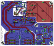
When one is not using C9, because of the FET input opamps, normally it should be shorted out.
But.. At this moment R10 could be just directly connected to the top (red) ground plane.. If You would just create a clearence in the ground plane solder mask, somewhere beside the R10 pin.. Then a zero ohm resistance could be plced there or simply a solder blob / bridge, directly connecting R10 to that sensitive ground..
Ciao, George
Last edited:
Joseph detected the change, which I requested years ago.
Dario, you found a way to do it, and I thank you for this and all your efforts.
Please invoice me for one pair of fancy R3's. I'll be happy to use them in this new build. I agree that the Caddocks have outstayed their welcome.
Peace,
Tom E
Dario, you found a way to do it, and I thank you for this and all your efforts.
Please invoice me for one pair of fancy R3's. I'll be happy to use them in this new build. I agree that the Caddocks have outstayed their welcome.
Peace,
Tom E
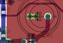
Dario,
Please be aware of the new R3/heatsink position in relation to chip mounting hole. It was always problematic. I can't tell for sure, but the new orientation looks like it might be even worse. If the resistor could be moved slightly off-center, mounting 3886 to heatsink would be much easier.
Peace,
Tom E
Great work, Dario.
It looks like it might be tight, but is it possible to include a hole for the old TO-220 R3 spacing? For example, I know that Pete is using the Ohmite TO-220. It's not a big thing if its not possible.
Hi Jac,Good idea, that would give people more options if possible.
I will look at it but anyway a TO220 resistor can still be mounted bending its leads...
Speaking of C1 and C2, when did you make the change to the 470uF decoupling caps as the schematics I've been looking at has 220uF caps, and how much of an effect did they have on mid frequencies?
If I remember correctly when BOM has been revised for 1.6.
Too much time passed I don't remember which difference made but it was introduced following other LM3886 designs and it did improve perceived performance.
Hi George,Had a close look. I find it very nice. Don't see problems so far.. Maybe still overlooking something but really looks good..
And.
nice to read
ThanksCOMPLIMENTI per i 500..!
Something like this?:Maybe one thing..
When one is not using C9, because of the FET input opamps, normally it should be shorted out.
But.. At this moment R10 could be just directly connected to the top (red) ground plane.. If You would just create a clearence in the ground plane solder mask, somewhere beside the R10 pin.. Then a zero ohm resistance could be plced there or simply a solder blob / bridge, directly connecting R10 to that sensitive ground..
I see an extra hole..?
YesAre we talking about the extra mounting hold in the middle?
You're welcomeJoseph detected the change, which I requested years ago.
Dario, you found a way to do it, and I thank you for this and all your efforts.
DonePlease invoice me for one pair of fancy R3's. I'll be happy to use them in this new build. I agree that the Caddocks have outstayed their welcome.
Following build guide suggested mounting method it's not problematic at all, even with the new bigger resistor and heatsink.Please be aware of the new R3/heatsink position in relation to chip mounting hole. It was always problematic. I can't tell for sure, but the new orientation looks like it might be even worse. If the resistor could be moved slightly off-center, mounting 3886 to heatsink would be much easier.
In any way this arrangement permits shorter return path for the feedback network and to not impair, as much as possible, current return from the LM3886.
Attachments

MassBoost;6263252 Speaking of C1 and C2 said:Years ago, maybe 2003 or so, Mauro childed me for this change. Said the value was for proper overload recovery. Said from testing this was the largest value that clipped properly. He saw these caps as bypass caps for the the 10,000 ufd reservoir caps.
Those versions used SIP package general purpose rectifiers. With dual bridge fast rectifiers this may be addressed.
I never told him about the 22 ufd FM caps I soldered directly to the LM3886 power pins. They were under the board out of sight.
Years ago, maybe 2003 or so, Mauro childed me for this change. Said the value was for proper overload recovery. Said from testing this was the largest value that clipped properly. He saw these caps as bypass caps for the the 10,000 ufd reservoir caps.
Those versions used SIP package general purpose rectifiers. With dual bridge fast rectifiers this may be addressed.
I never told him about the 22 ufd FM caps I soldered directly to the LM3886 power pins. They were under the board out of sight.
Heh nice, out of sight out of mind...
You can also clamp the LM3886.
With a piece of 6mm brass flat bar.
But there are also extra clamps for this attachment.
In my Solton SPA 150 it is also solved this way, only then is the brass rod used for quicker heat dissipation.
Jeff Rowland attached the LM3886 to the Model112 with a brass flat bar.

With a piece of 6mm brass flat bar.
But there are also extra clamps for this attachment.
In my Solton SPA 150 it is also solved this way, only then is the brass rod used for quicker heat dissipation.
Jeff Rowland attached the LM3886 to the Model112 with a brass flat bar.
Slight delay, worth it, though.
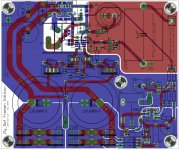
Since design have been modified significantly I'm double checking everything, fixing text orientation, optimizing small details and also introduced support for both lead spacing variants for z-foils (3.81 and 5.08 mm lead spacing).
Boards should be ordered by next wednesday.

Since design have been modified significantly I'm double checking everything, fixing text orientation, optimizing small details and also introduced support for both lead spacing variants for z-foils (3.81 and 5.08 mm lead spacing).
Boards should be ordered by next wednesday.
Attachments
- Home
- Group Buys
- My_Ref Fremen Edition GB (14th GB)