I am out! My motor (Thorens RDM57/12) wants 250mA... Sorry
Hi DieterK, sorry to hear that. You can however just boost the output of the board with an off board amplifier as I have previously indicated. If you look at Pyramid's SG4 thread you will find a suitable amplifier there. No problem if you do want out there are a couple of individuals interested in the group buy that missed the end of Feb close.
Is this group buy still happening? I'm very interested in getting in on a full kit, that is if it will work for a 5.5 watt motor.
Hi there, yes it is. I am just waiting for the PCB's to arrive. Yes a 110v 2 phase synchronous 5.5W motor should be perfect. If you want to proceeds send me a PM initially and I will advise as DieterK may wish to drop out.
Hi DieterK, sorry to hear that. You can however just boost the output of the board with an off board amplifier as I have previously indicated. If you look at Pyramid's SG4 thread you will find a suitable amplifier there. No problem if you do want out there are a couple of individuals interested in the group buy that missed the end of Feb close.
Hi DieterK
here are the components you would need:
Class D amplifier module - this is stereo so will drive 2 phases.
Then one or two transformers depending if you motor is one or two phases. A suitable transformer would be Triad VPT24-1040 25VA (24v secondary 115/240 primary). Connecting the secondary to the Class D amp outputs and the primary to your motor.
Update and Optional Enclosure
Hello fellow HiFi enthusiasts,
I have some positive and not so positive news.
I have in my possession the vast majority of the parts for your kits and assembled motor speed controller. However, due to the Corona virus the PCB’s which should have arrived this weekend are delayed in China. They are manufactured, but are awaiting shipping. Due to reduced airline, traffic there are delays. I am waiting on the supplier to provide me with a new ETA and I will update you when I have further news.
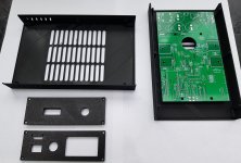
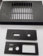
On a more positive note I have designed an external 3D printed enclosure for anyone who cannot mount the board in their plinth. Mains power via a switched fused IEC320 socket and a circular 6 pin connector to attach to motor and optionally power switch on turntable. (This then allows master on/off switching from existing TT main power switch if desired). The OLED & 33/45 rpm switch can optionally be mounted in this enclosure instead of the IR sensor box if that’s your preference. (I will also supply a blank front plate if you want to keep the switch & OLED in sensor box). The FFC cable to the external sensor/OLED/switch box will connect to the rear of this enclosure by means of a panel mount PCB/FFC socket combination. Access to serial USB is also facilitated for feature parameter adjustment.
I plan to offer these in black/silver grey to match system. The front and faces of the enclosure have a textured finish.
I am waiting for connectors etc. to actually test a board in the box for thermal performance and practicality.
Stay safe and happy listening.
Hello fellow HiFi enthusiasts,
I have some positive and not so positive news.
I have in my possession the vast majority of the parts for your kits and assembled motor speed controller. However, due to the Corona virus the PCB’s which should have arrived this weekend are delayed in China. They are manufactured, but are awaiting shipping. Due to reduced airline, traffic there are delays. I am waiting on the supplier to provide me with a new ETA and I will update you when I have further news.
On a more positive note I have designed an external 3D printed enclosure for anyone who cannot mount the board in their plinth. Mains power via a switched fused IEC320 socket and a circular 6 pin connector to attach to motor and optionally power switch on turntable. (This then allows master on/off switching from existing TT main power switch if desired). The OLED & 33/45 rpm switch can optionally be mounted in this enclosure instead of the IR sensor box if that’s your preference. (I will also supply a blank front plate if you want to keep the switch & OLED in sensor box). The FFC cable to the external sensor/OLED/switch box will connect to the rear of this enclosure by means of a panel mount PCB/FFC socket combination. Access to serial USB is also facilitated for feature parameter adjustment.
I plan to offer these in black/silver grey to match system. The front and faces of the enclosure have a textured finish.
I am waiting for connectors etc. to actually test a board in the box for thermal performance and practicality.
Stay safe and happy listening.
Attachments
Hi Toaster,
I took the liberty of ordering a few extra boards so you are in luck (but I will need to order more components). If you could fill out this Google Form I will send you a PayPal invoice with the deposit amount.
I took the liberty of ordering a few extra boards so you are in luck (but I will need to order more components). If you could fill out this Google Form I will send you a PayPal invoice with the deposit amount.
Hi there! Is it still possible to add an order to this GB, or is the first run already committed?
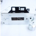
Hi, I'm still thinking about the packaging, and I wonder if this box will do, dimensionally?
I guessed at the cutout of the front panel, and it looks like the display will comfortably fit.
Disclaimer: I'm terrible at mechanical things and drillings and cuttings are my worst nightmare.")
I guessed at the cutout of the front panel, and it looks like the display will comfortably fit.
Disclaimer: I'm terrible at mechanical things and drillings and cuttings are my worst nightmare.
Attachments
Yes eactly. When installed its use is entirely optional.
Form submitted. I'm assuming the Linn switch connector can be specified- just in case it's ever needed- without having to use it?
That's a nice enclosure. The main PCB is 100 x 160mm so interior dimensions are fine. However, the display cut-out is too large for the OLED I supply. You could adapt with a bezel or blank off entirely if using the other OLED mounting option in the speed sensor case.
Hi, I'm still thinking about the packaging, and I wonder if this box will do, dimensionally?
I guessed at the cutout of the front panel, and it looks like the display will comfortably fit.
Disclaimer: I'm terrible at mechanical things and drillings and cuttings are my worst nightmare.
That's a nice enclosure. The main PCB is 100 x 160mm so interior dimensions are fine. However, the display cut-out is too large for the OLED I supply. You could adapt with a bezel or blank off entirely if using the other OLED mounting option in the speed sensor case.
I'm not decided yet; if I'd go the OLED in the sensor case route, then this box would be suitable, if the components are not much higher than 30mm (internal height = 42mm). And maybe I can use the case as a heatsink.

Hi Zung, Yes that would be fine. Board and component height 20mm on top and 5mm underneath. If you mounted the board on say 10mm stand-offs that would work nicely.
I'm not decided yet; if I'd go the OLED in the sensor case route, then this box would be suitable, if the components are not much higher than 30mm (internal height = 42mm). And maybe I can use the case as a heatsink.
- Home
- Group Buys
- Turntable Tachometer and motor speed controller