"A series choke may be troublesome, but it should be noted that using a series choke after a regulator doesn't make any sense anyway. It's a waste of money and space. If you are religious about chokes, put it before the regulator, that can make sense."
How does it make sense to take the high Z anode load and replace it with a low Z regulator and then put that high Z inductor before the regulator???
This all remains very confusing.
Ahh, I misunderstood, you use the choke as the anode load - I thought you wanted to use it to further smooth the regulator output.
The regulator does only need a small output cap, for stability, but not to smooth the output, that is already much smoother than a cap could be.
On the T-reg board it is 1uF in series with a small resistor to provide some losses needed for stability.
But if you feed a choke loaded amplifier, you DO need an extra cap at the regulator output to absorb the swings from the choke. That is no different from a non-regulated supply where you need capacitors on the B+ for the same purpose, in addition to smoothing the ripple on the high voltage.
I have not tried that but looking at the usual amp circuit it appears that 47uF will do. But you can use more.
Jan
Last edited:
I have done some simulations, but I can't reproduce the situation of the output of T-reg to rise above it's setting. The only way the regulator output voltage can rise is when the load current reverses, that the current tries to flow back into the regulator.*
Even with the inductive load of a choke loaded tube stage, that does not happen. So unless anyone comes up with a circuit that would show it, I assume that the report was incorrect.
Jan
* Note that T-reg needs at least 3mA minimum load. So if you run it without any load, the output will be too high.
Most likely the plate and presumably the following stage present enough real impedance effectively in series with the choke from the point of view of the regulator, to keep the regulator happy.
In other words the regulator sees the inductor in series with a big resistor.
No?
In other words the regulator sees the inductor in series with a big resistor.
No?
Last edited:
@schiirrn - can you post a schematic of your choke loaded amp stage?
Maybe I can do a sim.
Jan
I currently don't use a choke loaded stage that I plan on feeding with a T-Reg. What I do have in the works is a 2 stage mono amplifier as in the the simplified diagram attached earlier where I thought about using the regulators for setting anode voltages and decoupling of stages which for me usually takes priority (when thinking about regulators) before smoothing and providing a supply with even source impedance.
It will take a few weeks but I can get back with measurements when a breadboard is built.
Last edited:
I'm currently looking at power for a cascode front stage and a push pull back end.
How much voltage drop headroom is required for the board?
I see you've essentially made a negative by re-referencing the board - would there be an issue running -320V -> +320V, across two regulators referenced to the same ground voltage?
The output stage is running up to 240mA each channel at 200V B+. I see you have current limiting - if the negative board is running re-referenced is it providing current limiting on the B- rail in a B- to B+ scenario? (if the regulator is regulating the return if it's shifted?)
Lastly I'd be using something like a CLC on each rail. How would at affect the board running with B+ and B- (as a B+ running with GND as B+)?
Last edited:
The thing to be aware of when you use one as a neg reg, then connect the outputs for +300 - GND - -300 is that the inputs to the two boards must be separate. That means two transformer secondaries and rectifiers, so you can't use a center tapped secondary (unless you open up the center tap so you have two separate windings and full wave rectifiers).
Other than that, you should have no issues and the current limiting will work fine on each board.
Jan
Other than that, you should have no issues and the current limiting will work fine on each board.
Jan
The thing to be aware of when you use one as a neg reg, then connect the outputs for +300 - GND - -300 is that the inputs to the two boards must be separate. That means two transformer secondaries and rectifiers, so you can't use a center tapped secondary (unless you open up the center tap so you have two separate windings and full wave rectifiers).
Other than that, you should have no issues and the current limiting will work fine on each board.
Jan
Thank you, it confirmed my concern with the rail-to-rail requirement.
More tests with parafeed output stage to come
Just seeing this b/c I had notifications turned off.
I've been meaning to return to this. I never managed to get the reg working when feeding a parafeed output stage (choke-loaded power tube, with parafeed cap after choke feeding the OPT). I tried it in two different parafeed amps without success. But it worked flawlessly in tests into a purely resistive load.
My guess is that my problem is the one identified by Jan in the quote: I need the plate choke to swing voltage higher than the output of the reg. Want I want to try is moving the reg before the huge reservoir film cap (1500 uf) I have in the PS filter, with the hope that the huge capacitance will shield the reg output from the anode voltage swings.
I'll report back after trying that. But it may be some weeks before I get to it.
cheers, Derek
Yes, post #241 ff for example, the issues Derek is/was (?) having.
In post #247 you wrote:
"I believe that the problem with the large inductive load is the fact that an inductor tends to create a large varying voltage with varying current. If that voltage gets above the T-reg output, it can't 'go' anywhere - a regulator is designed to source current, not to sink it."
...
Just seeing this b/c I had notifications turned off.
I've been meaning to return to this. I never managed to get the reg working when feeding a parafeed output stage (choke-loaded power tube, with parafeed cap after choke feeding the OPT). I tried it in two different parafeed amps without success. But it worked flawlessly in tests into a purely resistive load.
My guess is that my problem is the one identified by Jan in the quote: I need the plate choke to swing voltage higher than the output of the reg. Want I want to try is moving the reg before the huge reservoir film cap (1500 uf) I have in the PS filter, with the hope that the huge capacitance will shield the reg output from the anode voltage swings.
I'll report back after trying that. But it may be some weeks before I get to it.
cheers, Derek
Last edited:
Help with diagnostics?
I have two T-Reg V5s that I'm using for plate voltage on my HHScottt 222C. I'm having trouble with one of them.
That amp has four 7189 pentode output tubes at 420V, datasheet says a maximum 105mA plate current in push-pull operation. I have one T-Reg per pair, maximum signal current for each pair is 210mA.
I carefully looked over both units before testing. When I tested them under actual operating conditions, temporarily connected with alligator clips, they worked fine in bringing the raw voltage from about 440V to 420V and held steady for a good amount of time.
However, after I installed them in a more permanent fashion, I discovered a hidden cold solder joint on the output from one of the units meaning it was not connected to the load for a few minutes. That one now doesn't regulate properly. The other unit is fine.
Here's some basic data based on what I've found in previous troubleshooting comments on this thread:
R16 = 2.2 Ohm, 1W (should limit current to 400mA, yes?)
R11 = 750 kOhm (provides about 420V with 117VAC)
Raw V in: 443
V out: 431 (adjusting trimpot makes no difference)
I/O difference = 12V
The Gate to Source voltage for FDP, Q1 = 4.5V.
U2 pin 2 to output = 0
U2 pin 3 to output = 0
U1 pin 1 to ground = 431
U1 pin 2 to ground = 443
U1 pin 3 to ground = 443
U1 pin 1 to pin 3 = 11.4
The LED is illuminated.
I'm not sure if it's safe to take U2 out of the working unit and put it into the non-working unit in case the fault takes that one out too.
Is my guess that the FDP got zapped when the T-Reg was not connected to the load? Or is the AD8031 toast? Or both? My inclination is to replace both ICs and both MOSFETs even though that's throwing parts at the problem.
Any further hints would be appreciated. I'll provide any further measurements as requested.
Thanks for getting back to me so quickly.
I found the problem. I had mistakenly installed the D4 5.6V Zener in the D5 12V Zener position and vice versa. Some of this newfangled solid state stuff is where I lack a bit of knowledge and experience. Had I not checked those zener voltages I'd have never found that problem. From now on I use my 5X magnification optivisor when handling those tiny zeners.
Both units are now functioning perfectly and my stereo sounds great.
For the record, for anyone running across the above comments while troubleshooting, the voltages you requested (after having corrected the Zener diode error) are as follows:
U2 Pin 7 to Pin 4 = 7.52V
Voltage across R13 = 2.1V
Voltage across D4 =5.4V
Voltage across R13 and D4 = 7.5V
The left unit is taking in 432V, output 418V
Right unit is 434V in, 421V out.
Thanks for pointing me in the right direction.
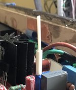
One thing that’s been bugging me, I can’t find my trimpot tool with the recessed blade for those Bourns trimpots with the tiny slotted adjusting screw. I took a piece of 3mm hollow plastic tubing, reamed out the inner diameter to fit over the screw snugly and fastened it with CA glue (aka crazy glue), being careful to not let the glue run onto the screw and trimpot body. I can now more easily adjust those 25-turn trimpots by turning the plastic rod instead of a flat blade adjustment tool that keeps slipping off, a bit hazardous if you use metal screwdriver (which I do not recommend) that could cause a short circuit. That’s particularly helpful with that heat sink at 434V so nearby.
Attachments
Thanks for getting back to me so quickly.
I found the problem. I had mistakenly installed the D4 5.6V Zener in the D5 12V Zener position and vice versa. Some of this newfangled solid state stuff is where I lack a bit of knowledge and experience. Had I not checked those zener voltages I'd have never found that problem. From now on I use my 5X magnification optivisor when handling those tiny zeners.
Both units are now functioning perfectly and my stereo sounds great.
For the record, for anyone running across the above comments while troubleshooting, the voltages you requested (after having corrected the Zener diode error) are as follows:
U2 Pin 7 to Pin 4 = 7.52V
Voltage across R13 = 2.1V
Voltage across D4 =5.4V
Voltage across R13 and D4 = 7.5V
The left unit is taking in 432V, output 418V
Right unit is 434V in, 421V out.
Thanks for pointing me in the right direction.
Well done! Those voltages look OK.
Jan
One thing that’s been bugging me, I can’t find my trimpot tool with the recessed blade for those Bourns trimpots with the tiny slotted adjusting screw. I took a piece of 3mm hollow plastic tubing, reamed out the inner diameter to fit over the screw snugly and fastened it with CA glue (aka crazy glue), being careful to not let the glue run onto the screw and trimpot body. I can now more easily adjust those 25-turn trimpots by turning the plastic rod instead of a flat blade adjustment tool that keeps slipping off, a bit hazardous if you use metal screwdriver (which I do not recommend) that could cause a short circuit. That’s particularly helpful with that heat sink at 434V so nearby.
That is a good solution. My solution is a bit different: I kept on buying (and losing) cheap insulated trim screwdrivers until I started to find them again because there are so many floating around. It's a small amount that can be used to pad a Mouser order to get over $50 for free delivery. Probably half a dozen ;-)
Jan
Last edited:
"Should be no problem" and "some reports with successsful use" still make it sound as if something like the attached schematic might or might not work...
The amplifier is built and works. Both regulators have a load resistor at the output to draw necessary minimum current. No oscillations. Stable output voltage.
I'm trying to figure out how to use PSU designer II to design a PSU that would set the correct voltage coming into the Voltage Regulator. The last component (R2) is meant to represent the T-Reg voltage regulator. I have a couple of questions about that.
Glenn

- Should the load representing the T-Reg be resistive or a constant current load?
- And what would be the appropriate values (either resistive or constant current) to most accurately represent the T-Reg?
Glenn
- Home
- Group Buys
- Group Buy for Jan's high voltage regulator