Probably.
If nodemcu is 5V tolerant (it seems to be - there has been some discussion about it on hackaday), you can just pull up the SDA and SCL to 5V with resistors. Note that the pull-up resistors are not designed into the volume control board.
If nodemcu is not 5V tolerant, then the pull-up has to be to 3.3V, and it may or may not work with the 5V powered PCF8574. The datasheet says (page 16) that the minimum HIGH level input voltage on SDA and SCL is 0.7Vdd, which would be 3.5V for 5V Vdd. It might still work though.
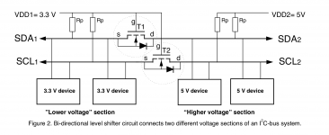
In case it doesn't work, you can always make a level converter with two N-channel MOSFETs and four resistors as in the attached schematic, borrowed from Philips Application Note 97055, "Bi-directional level shifter for I2C-bus and other systems". You can also use one readily available from the usual sources, such as SparkFun, Adafruit, eBay, or Velleman.
Or you could power the PCF8574 and from 3.3 volts and use 3.3V relays, but that may exceed PCF8574's current limit when all relays are engaged, as 3.3V relays generally need more current than 5V relays.
If nodemcu is 5V tolerant (it seems to be - there has been some discussion about it on hackaday), you can just pull up the SDA and SCL to 5V with resistors. Note that the pull-up resistors are not designed into the volume control board.
If nodemcu is not 5V tolerant, then the pull-up has to be to 3.3V, and it may or may not work with the 5V powered PCF8574. The datasheet says (page 16) that the minimum HIGH level input voltage on SDA and SCL is 0.7Vdd, which would be 3.5V for 5V Vdd. It might still work though.
In case it doesn't work, you can always make a level converter with two N-channel MOSFETs and four resistors as in the attached schematic, borrowed from Philips Application Note 97055, "Bi-directional level shifter for I2C-bus and other systems". You can also use one readily available from the usual sources, such as SparkFun, Adafruit, eBay, or Velleman.
Or you could power the PCF8574 and from 3.3 volts and use 3.3V relays, but that may exceed PCF8574's current limit when all relays are engaged, as 3.3V relays generally need more current than 5V relays.
Attachments
Last edited:
Hey Guy's, I could use your thoughts on this.
I'm just finished my boards and have them installed in a temporary case for testing. All the voltages, etc seem fine and everything is working OK. The problem I'm having is with the volume control. When switching between positions 7-8 and 11-12, the volume goes to full in the middle of the switch. In fact if I rotate the switch slowly you can see all the LED's light. So, the LED's go from 7 to 15 then 8. Same at positions 11-12. Any ideas at what is going on? A bad encoder maybe?
I'm just finished my boards and have them installed in a temporary case for testing. All the voltages, etc seem fine and everything is working OK. The problem I'm having is with the volume control. When switching between positions 7-8 and 11-12, the volume goes to full in the middle of the switch. In fact if I rotate the switch slowly you can see all the LED's light. So, the LED's go from 7 to 15 then 8. Same at positions 11-12. Any ideas at what is going on? A bad encoder maybe?
What's going on is the encoder changes the code from 7(0111) to 8(1000), but the change in different bits is not simultaneous, so it goes 0111->1111->1000. In the middle, unstable position, it is full volume and all LEDs are on. With 11->12 it is probably 1011->1111->1100. I am not sure how to remedy this, however. Perhaps someone else experiences the same issue?
Hey Alexy,
Thanks for replying. Ya, I understand how the encoder works. For some reason I was not expecting this. If you rotate the volume fast enough the pop is not too noticeable. But if go too slow it can be a little startling. I have it in my main system now for a listen. The other issue I have is it's too loud. I have it turned down to 1 and its still louder then I want. I may replace this with a regular pot until I have time to figure out a remote volume for this. Thanks again.
Thanks for replying. Ya, I understand how the encoder works. For some reason I was not expecting this. If you rotate the volume fast enough the pop is not too noticeable. But if go too slow it can be a little startling. I have it in my main system now for a listen. The other issue I have is it's too loud. I have it turned down to 1 and its still louder then I want. I may replace this with a regular pot until I have time to figure out a remote volume for this. Thanks again.
To reduce gain, you need to reduce R12/R22. From Hans Polak’s original article:
If you replace the resistors with, say, 2kOhm, the maximum gain will be 0dB, and the minimum gain will be -30dB. The easiest is to solder a couple of 4kOhm or so resistors (SMT 0805 or leaded) on top of R12 and R22 in parallel with them.Gain can never be more than +6dB and never be less than -24 dB [...]. The fixed feedback resistor R12/R22 of 4K Ohm attached to the output amp determines the maximum gain of 6dB, but can easily be adapted to one’s need.
Last edited:
I have a full set of boards with the SMT soldering completed. If it is ok, I would like to offer it up at exactly the same price it was offered to me. $97 shipped via paypal. Please let me know if anyone would like them.
I'm interested in your boards. I also send a PM.
- Home
- Group Buys
- Interest in PCBs for Bruno Putzey's Preamp and Hans Polak's relay volume control