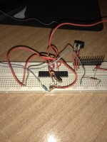
I used an arduino nano to burn the bootloader .
Now i see a blinking led connected to pin 19 of atmega328.
I think this say that bootloader is present.
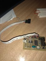
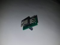
I will use this diy FTDI to load the sketch.
Now i see a blinking led connected to pin 19 of atmega328.
I think this say that bootloader is present.
I will use this diy FTDI to load the sketch.
Attachments
Last edited:
Hi, just a question, I have started populating the protection boards, R8 is a 2512 SMD part but the only other found in thr bag is written 2201 (2k2) but the BOM says 1k2, is the value supplied correct or the value mentioned in the build guide wrong? I will do a small check on the rest of the parts for any other mismatch if any and write back for any advice.
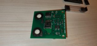
Thanks. The small sensor pcb and thesensor IC should be sokderded with the pins alternated? Could you post a photo just to make sure I will put the boards ok.
Regards, Florin
Thanks. The small sensor pcb and thesensor IC should be sokderded with the pins alternated? Could you post a photo just to make sure I will put the boards ok.
Regards, Florin
Hi, just got my notice from the post office that I have a package of about half of kg, probably the parts kit, is it any way to check for the binding posts?
Thanks,
Florin
Hi Florin,
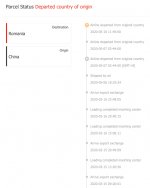
I have contacted the logistics - they say deliveries are heavily delayed due to the coronavirus issues and overall aviation freeze.
Attached is what the tracking system is showing (tracking number is RE029679788CN).
Sorry for such a long time waiting - in the worst case we will re-sent the product or offer a refund. Although I'm still hoping you get the parcel soon.
Cheers,
Valery
Attachments
Hi, just a question, I have started populating the protection boards, R8 is a 2512 SMD part but the only other found in thr bag is written 2201 (2k2) but the BOM says 1k2, is the value supplied correct or the value mentioned in the build guide wrong? I will do a small check on the rest of the parts for any other mismatch if any and write back for any advice.
Thanks. The small sensor pcb and thesensor IC should be sokderded with the pins alternated? Could you post a photo just to make sure I will put the boards ok.
Regards, Florin
It sounds like I may have sent the wrong resistor for R8. It should be 1.2K. I hope my inventory isn't messed up, otherwise there will be a few others with the same problem. Are all the other parts correct?
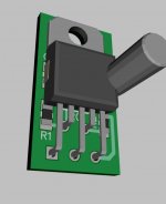
I'll need to do some digging to find a picture of an assembled temperature sensor. The sensor mounts under the board and the pins are to be bent up 90 degrees. The pins are bent at two different lengths, like in the 3D image except they are bent forward instead of back.
Attachments
") .
.Ho, I managed to make a full inventory today on the kit sent, I will e-mail you the contents received, I did manage to put together allmost both the speaker boards without R8 unfortunatelly, like I have said some resistors I will manage to get here, so it wont be such a hassle. I will send the list to you tommorow, can I program the controller later? If I start putting the other parts on the board and write the sketch later, would that be an issue? I am asking because one of the parts missing is the crystal Y2. I will try and find it on TME.eu , its a 16Mhz from Murata, I will try and locate it with the name from the guide, hopefully they have it, if not can I use any 16Mhz crystal? Any key specs to look for ?
Thanks,
FLORIN
Thanks,
FLORIN
Attachments
Last edited:
I remember putting the resonator in the kits but it's pretty easy to loose, I may have dropped it before sealing up the bag. You can usually install the bootloader without the resonator installed. The Atmega328 has a built in 12MHz crystal (if I remember correctly) that operates until the bootloader is installed. If not it can be done any time.
Here's the resonator I normally use, but there are others that will fit. CSTNE16M0V530000R0 Murata Electronics | Mouser Canada I don't see anything on TME's sit that looks suitable though.
Here's the resonator I normally use, but there are others that will fit. CSTNE16M0V530000R0 Murata Electronics | Mouser Canada I don't see anything on TME's sit that looks suitable though.
Hi Valery, could you please send if you have a drilling pattern for the simplestark amplifier boards ( for the heatsink, if you have one that marks the center of the hole). Also for the fuses on the control board should I assume that F1 means 1A, and F3 is 3A? It would be specific to the trabsformer size(power) , but given that a 200VA or 250VA transformer should be enough for one chanel 4A would be enough not to blow.
Thanks
Florin
Thanks
Florin
F1 and F3 on the control board are just part reference numbers to match to the schematic. Fusing needs to be selected to match the transformer and mains voltage selected. For F1 a 0.1A slow blow fuse should work for 240V mains. F3 depends on your supply transformers. If you are using 2 x 200VA transformers it would be 400VA / 240VAC mains x 150% for a 2.5Amp slow blow fuse.
Hi Valery, could you please send if you have a drilling pattern for the simplestark amplifier boards ( for the heatsink, if you have one that marks the center of the hole). Also for the fuses on the control board should I assume that F1 means 1A, and F3 is 3A? It would be specific to the trabsformer size(power) , but given that a 200VA or 250VA transformer should be enough for one chanel 4A would be enough not to blow.
Thanks
Florin
Hi Florin, please see the drilling template attached.
What I did building my prototype - I have printed this on a piece of paper, cut it to match the board outline, mounted the template on a heatsink with scotch tape, and drilled through the paper 2.7 mm holes. Then tapped with M3 tap.
Cheers,
Valery
Attachments
Hi, in the build guide for the Compact power supply R14 doesnt show in the parts list, the PCB has a place for it and is listed as as 1206 10K resistor. Would that be right?Also for the heatsinks did you guys use some kind of isolator to keep the metal side of the heatsink from touching the PCB traces? If so what? I could use some kind of plastic or silicone washer to raise the heatsink from the board.
Also the 0.47ohm resistors showed in the BOM are just 1W, it's quite small wattage, should these be at least 3W maybe?
On the control board the ceramic resonator does it have a right orientation? There is a mark on it in one side , i have considered that pin 1 , the pin that goes to the pin7 of the 328 controller, is that right?
Thanks,
Florin
Thanks for the tip, I'll update the build guide. 10k would work fine for R14. I've also added a note to the build guide for R15 and R16. They are pull up resistors for the I2C bus. There only needs to be one pair of those resistors installed in the whole system and there are a pair on the control board, so you don't need them.
I usually just leave the heatsink slightly above the board when I solder it in, but you could space them up with a couple nylon washers if you like.
The Simpelstark amps have good PSSR, you could put a couple jumper wires in place of the 0.47R resistors. 1W is fine there if you want to use resistors, there are four in parallel sharing the load which will likely average less than an amp between them all so they won't be dissipating any heat.
The resonator orientation doesn't matter. Ground is in the middle, resonator connections on either side of it.
Hi, I just started testing the boards, the build guide says that at first start the compact power supply should measure at the output the voltage, I have zero, so the mosfets are not conducting, the board has no connection yet to the control board. Nothing is getting warm, no smoke nothing out of the ordinary apparently is going on.
Thanks,
Florin
Thanks,
Florin
- Home
- Group Buys
- Simpelstark+ ODNF amplifier boards GB