Sorry for the delay in getting this amp built. The assembly house tells me that they have the pick and place machine loaded now and are working on some details of scaling the placement file correctly. This is for the verification build before the full production run. We are getting close...
Thanks for your patience!
Thanks for your patience!
The two holes for mounting the bottom side heatsink or thermal pad spacer are 3mm dia holes spaced 36mm apart ctc. A 12mm wide x 3mm thick aluminum strip can work but note that there needs to be either a small elevated mesa on the flat surface to provide clearance for the SMT capacities mounted nearby as they are slightly higher than the TPA3255 chip. Conveniently, a copper core TE Connectivity Faston tab has the right dimensions of just covering the thermal pad of the TPA3255 and not being bigger than the width of the chip. I snipped the TH solder leg ends of the Faston tab off. I am actually using two of them to give about 2mm clearance between the heatsink and the IC. For testing I am using a small fan cooled GPU cooler with 12v fan. I added a 2W 100R resistor in series with the fan lead to slow it down to almost inaudible levels. The main amp has a 12v power output that I tapped off. It doesn’t seem to cause any motor noise pickup issues based on FFTs that I have seen.
Make sure you use thermal heatsink paste between the spacers and chip and heatsink. On a build where the thermal pad will be connected to a grounded chassis, make sure you use a non conductive insulator pad to prevent the thermal pad ground from directly contacting chassis ground to prevent ground loop hum. Ceramic insulator spacers are good for this. They are more thermally conductive than silicone and tougher. However, silicone can work fine. We are not talking about a huge load unless you plan on running full bore 200w per channel rms. In that case, 20w per channel or 40w total must be dissipated from that pad assuming 90% thermal efficiency. 40w is on the high end of even a typical TO247 MOSFET running in Class A. But normal music listening levels of say 40wrms is only 4w and is nothing for this type of thermal pad.
Some photos of how I installed my Faston thermal pad with a fan cooled heatsink are below.
Thank you very much. Thats a lot to think about. Did you use some sort of glue to attach the faston tabs to the TPA and heatsink?
Thermal paste holds it in place.
An aluminum thermal spacer to facilitate chassis based cooling seems like a good candidate for an Al 3D printed part.
How does it compare to AliExpress boards that go for around 60e?
TPA3251 / TPA3255 Digital Power Amplifier Board 1/2/4 Channel 135W / 175W / 315W / 600W on AliExpress
TPA3251 / TPA3255 Digital Power Amplifier Board 1/2/4 Channel 135W / 175W / 315W / 600W on AliExpress
How does it compare to AliExpress boards that go for around 60e?
TPA3251 / TPA3255 Digital Power Amplifier Board 1/2/4 Channel 135W / 175W / 315W / 600W on AliExpress
Read the thread. There are favorable comparisons.
How does it compare to AliExpress boards that go for around 60e?
TPA3251 / TPA3255 Digital Power Amplifier Board 1/2/4 Channel 135W / 175W / 315W / 600W on AliExpress
Read the thread. There are very favorable comparisons.
How does it compare to AliExpress boards that go for around 60e?
TPA3251 / TPA3255 Digital Power Amplifier Board 1/2/4 Channel 135W / 175W / 315W / 600W on AliExpress
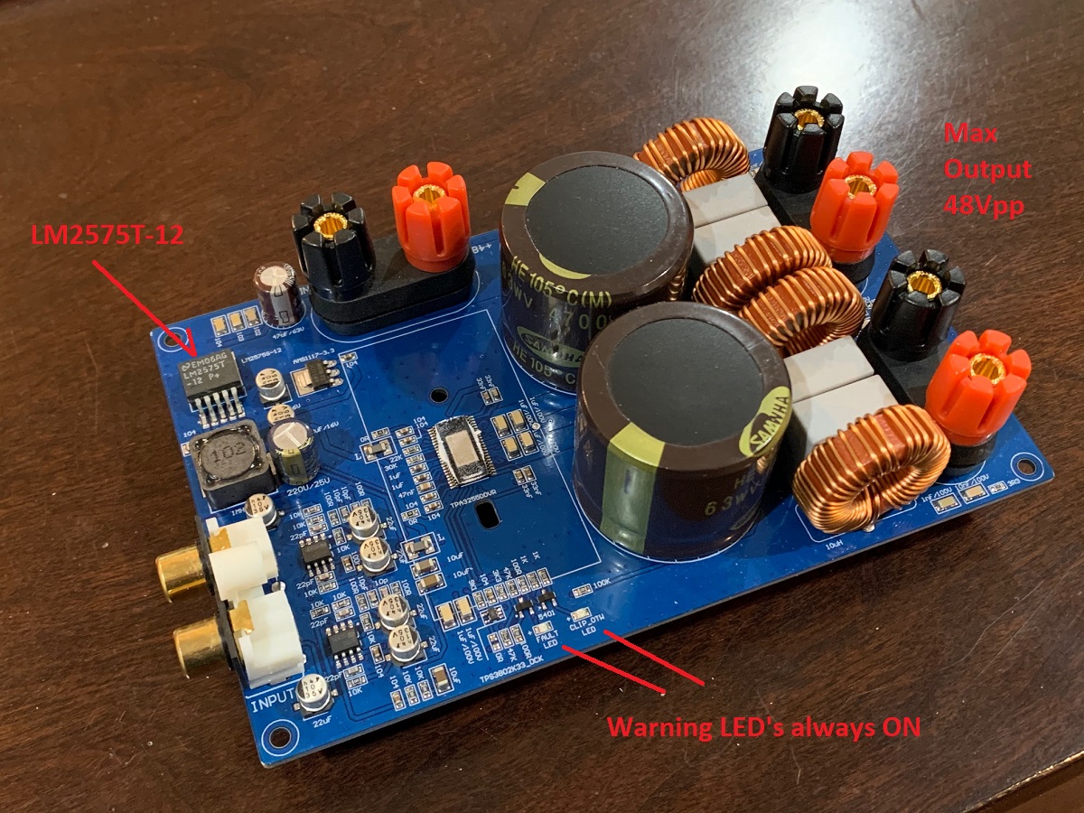
That board has errors on it that prevent it from being a practical amp. I bought two from different vendors and one was on Amazon. Still same problem because same layout.
1. The error lights for fault and OTW are always on when operating normally. How useful is that?
2. The amp has no remote reset capability, so if your input RCA has a glitch, the amp goes onto protect error mode and shuts down. The only way to reset is to unplug the power input. That is every inconvenient as the errors can happen with something like hot plugging in the RCA to a source.
3. I was unable to get more than 48Vpp out of it with a 51v PSU. I believe the hardwire soldered or layout based setup mode jumpers were incorrect and so it is not working in BTL mode which should give a swing of close to 2x48v minus MOSFET dropout on each end or 96v-8v or +/-78v theoretical max or 27.6Vrms for 190w into 4ohms.
4. It has an LM2575T-12 switching step down regulator for make 12v. That’s only good for 40V max input. It needs the LM2575HV-12 version which can go to 60v input. So I suppose the regulator must be sort of working because it makes music with a 48v to 51v supply, but who knows what the regulator is doing in terms of regulation.
5. The measured harmonic distortion profiles were not close to the specified levels of the TI reference design.
Basically, I can’t believe they went into production of tens of thousands of these boards without anyone catching these glaring errors.
The discussion appears to be coincident that the only board that can compete with the TI reference is the 3e Audio board, though being not as versatile. And most probably this GB one ") . Most of the other ones are lacking of quality especially of the output inductors, 'lytics etc.
. Most of the other ones are lacking of quality especially of the output inductors, 'lytics etc.
Best regards!
. Most of the other ones are lacking of quality especially of the output inductors, 'lytics etc.Best regards!
That board has errors on it that prevent it from being a practical amp. I bought two from different vendors and one was on Amazon. Still same problem because same layout.
1. The error lights for fault and OTW are always on when operating normally. How useful is that?
2. The amp has no remote reset capability, so if your input RCA has a glitch, the amp goes onto protect error mode and shuts down. The only way to reset is to unplug the power input. That is every inconvenient as the errors can happen with something like hot plugging in the RCA to a source.
3. I was unable to get more than 48Vpp out of it with a 51v PSU. I believe the hardwire soldered or layout based setup mode jumpers were incorrect and so it is not working in BTL mode which should give a swing of close to 2x48v minus MOSFET dropout on each end or 96v-8v or +/-78v theoretical max or 27.6Vrms for 190w into 4ohms.
4. It has an LM2575T-12 switching step down regulator for make 12v. That’s only good for 40V max input. It needs the LM2575HV-12 version which can go to 60v input. So I suppose the regulator must be sort of working because it makes music with a 48v to 51v supply, but who knows what the regulator is doing in terms of regulation.
5. The measured harmonic distortion profiles were not close to the specified levels of the TI reference design.
Basically, I can’t believe they went into production of tens of thousands of these boards without anyone catching these glaring errors.
Hi X
This AliExpress link is to the 3e Audio boards, not the run of the mil AliE boards to which you attribute certain errors!
TPA3251 / TPA3255 Digital Power Amplifier Board 1/2/4 Channel 135W / 175W / 315W / 600W on AliExpress
Sorry, my mistake - as I did not know they were on AliExpress (thought was only eBay before) but I did say “Blue” boards that look like this:

The 3e boards don’t have any of these issues although differences probably more in output inductor and quality of PCB (2mm thick, 2oz copper, and layout with via stitching by JPS64). But one feature not on 3e board is Post Filter Feedback (PFFB) which gives the best performance in terms of distortion.
The 3e boards don’t have any of these issues although differences probably more in output inductor and quality of PCB (2mm thick, 2oz copper, and layout with via stitching by JPS64). But one feature not on 3e board is Post Filter Feedback (PFFB) which gives the best performance in terms of distortion.
Last edited:
Sorry, my mistake - as I did not know they were on AliExpress (thought was only eBay before) but I did say “Blue” boards that look like this:
The 3e boards don’t have any of these issues although differences probably more in output inductor and quality of PCB (2mm thick, 2oz copper, and layout with via stitching by JPS64). But one feature not on 3e board is Post Filter Feedback (PFFB) which gives the best performance in terms of distortion.
Did you mean to say 1oz (2oz is recommended in data sheet, so that should be good thing).
My boards are 2oz copper - extra thick. No, the layout is not open source. The PCBs are available bare for $38. You would save yourself a lot of effort as it has been tested and verified to work. It also sounds great.
The PCBs are here:
TPA3255 Reference Class D amplifier PCB | Etsy
A fully assembled and ready to run board with genuine Mouser-sourced BOM and assembled in the USA amp board is also available for $227 here:
RTR TPA3255 Reference Class D amplifier | Etsy
The PCBs are here:
TPA3255 Reference Class D amplifier PCB | Etsy
A fully assembled and ready to run board with genuine Mouser-sourced BOM and assembled in the USA amp board is also available for $227 here:
RTR TPA3255 Reference Class D amplifier | Etsy
Last edited:
I did a full power test to see where clipping occurs. 51v DC-DC from 12v battery as power source for 51vdc. Driving with 1kHz sine wave from a pocket DAP and headphone amp through THAT1646 SE to Balanced line drivers Amp connected to EBG 300w 10ohm resistor cooled with CPU cooler. I got 32.1Vrms from a Fluke 116 True RMS DMM, that's about 90.1Vpp. The Oscope showed closer to 100Vpp. If this were driving 4ohms, it would be about 190w, maybe 200w.
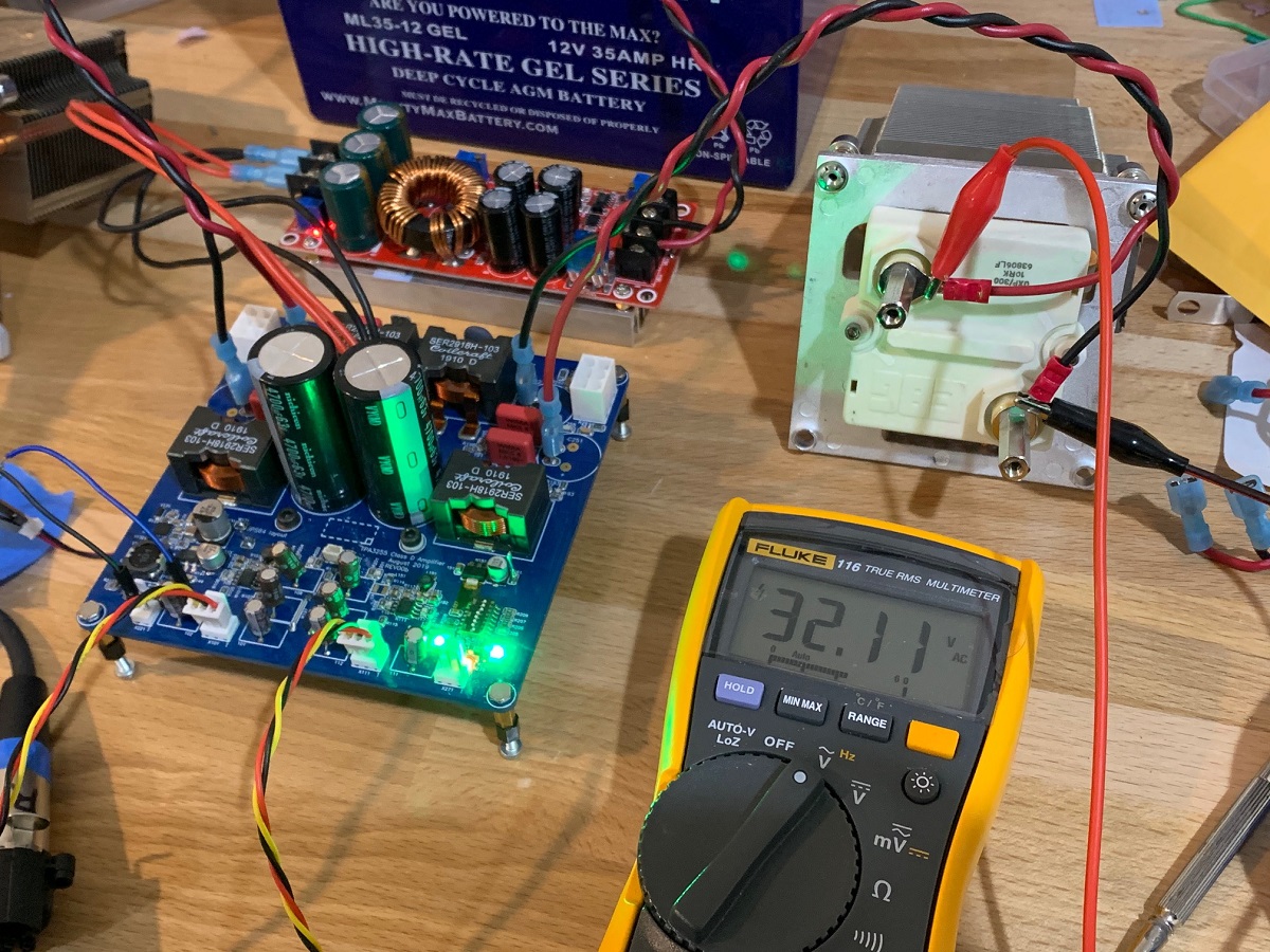
Here is Oscope screenshot - this is right at onset of clipping, so starting to get a little ragged at the peaks:
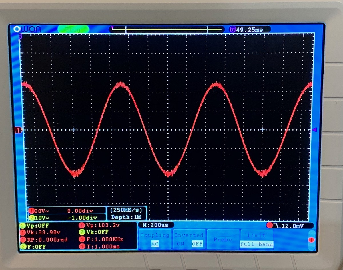
Into 10ohms, this is 103Wrms. This amp can definitely make some power.
Here is Oscope screenshot - this is right at onset of clipping, so starting to get a little ragged at the peaks:
Into 10ohms, this is 103Wrms. This amp can definitely make some power.
Last edited:
Hi XRK and all. I still haven't build my amp, but I still have my PCB 
Actually I'm in own houses business, sell here and I will build a little new one in the next months. New one will have a partial solar installation, I think based on Pylontech US3000 lithium battery.
As I'd like to avoid DC-AC-DC conversion for my TPA, and that lithium unit works almost with 48V, I'd like to have your point of view on that.
It seems US3000 can rise up to 53.5V (45 ~ 53,5) depending on its charge, do you think it will be safe for the TPA if I plug these two together ?
I don't know if I'll need caps between the Pylontech unit and the TPA PCB cause there will be a few meters between them, how many µF do you think if needed ?
I don't find a lot of advices on this particular configuration so perhaps you can help me
- Home
- Group Buys
- TPA3255 Reference Design Class D Amp GB