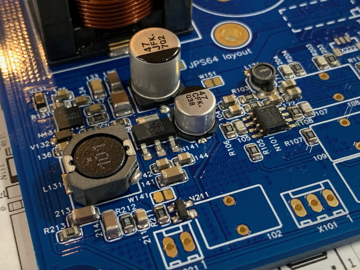
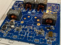
I finally had some time to do some SMT soldering of this amp. The top side SMT parts are all done, now need to flip over and solder the TPA3255 and a few more ancillary resistors and caps.

Attachments


Don't forget the crimp contacts.
Me forget to get crimp contacts, and miss a chance to play with my crimp tool collection?!
")
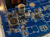
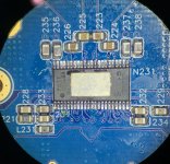
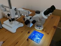
The new microscope was not needed for assembly (except for installing the barely visible polarity markings of the little LEDs) - but made double checking the solder joints a breeze. Under magnification, formerly beautiful reflow joints all look kind of ugly. Cold solder joints are easy to spot with a scope though.
Attachments
Last edited:
Not many but 70 unique parts makes for a slow assembly. I should have organized the parts by type across the whole board rather than working from inside to outside perimeter. Don’t know how many times I switched on/off installing 0.1uF bypass caps and 10k resistors. I’ll be smarter next time!
Hi Do,
Thanks! I use a non stick fry pan over a $10 electric hot plate to preheat the bottom of the board to about 130C (measured with IR thermometer). Then I apply 300C hot air from a SMT gun from above. This lets me work and melt section by section and reduces the time components get above the melt temp. The liquidus melt temp depends on paste. I normally use PbSn based paste as it works better. But this time, happened to have some Pb-free paste already in my applicator gun.
I use pretty inexpensive hot air pencil like this:
858D+ Hot Air Soldering Station 110V 700W LED Digital Solder Heat Gun Rework ESD SMD SMT Welding Repair https://www.amazon.com/dp/B07F3WLX7H/ref=cm_sw_r_cp_api_i_teyIDbR60NJ0Z
The paste extruder gun is an “I-Extruder” digitally controlled one. It works very well for big projects and is precise. I would have made even cleaner joints except using old paste and it occasionally clogged so not as consistent as a new tube of paste. This applicator is pricey but worth it for large projects. You don’t need a stencil doing it this way for development.
I-EXTRUDER - Airless Solder Paste Dispenser with Pick & Place Feature
Video demonstration here:
YouTube
Good Swiss stainless steel tweezers and magnifying goggles are a must.
Fine copper braid (NTE brand) and liquid flux (precision tip applicator) and chisel tip soldering iron for cleaning up excess on pins is also useful.
Specific paste that I like includes:
MG Chemicals 4860P 63/37 No Clean, Leaded Solder Paste, 35 g (1.2 oz) Pneumatic Dispenser (Complete with Plunger & Dispensing Tip) https://www.amazon.com/dp/B00M1RC0YY/ref=cm_sw_r_cp_api_i_znyIDbDPMW5DT
This works for smaller projects where you manually use thumb pressure to apply paste. More than 50 parts and your finger will cramp with a manual applicator.
I think for this project I was using Sn42Bi58 no clean paste solder from iExtruder:
Sn42/Bi58 No Clean Solder paste - I-Extruder solder paste dispensers
One more thing, for this project there are two sides so how do I install the bottom side parts now that the top is already populated?
I use the hot air pencil to preheat the bottom of the board (the top side now) to get it warm enough to apply heat from the top to melt it.
They make special IR/hot air preheater rework stations which would be handy, but for this project not needed. It would be a substitute for the fry pan.
New & Improved X-Tronic MODEL 5040-XR3 All In One Hot Air Rework Soldering Iron Station With Preheater. Now Includes Plug & Play Hot Air Gun With Iron Holder & Sponge Cleaner https://www.amazon.com/dp/B019LQ5YUE/ref=cm_sw_r_cp_api_i_KEyIDbBFVGB1Z
Last edited:
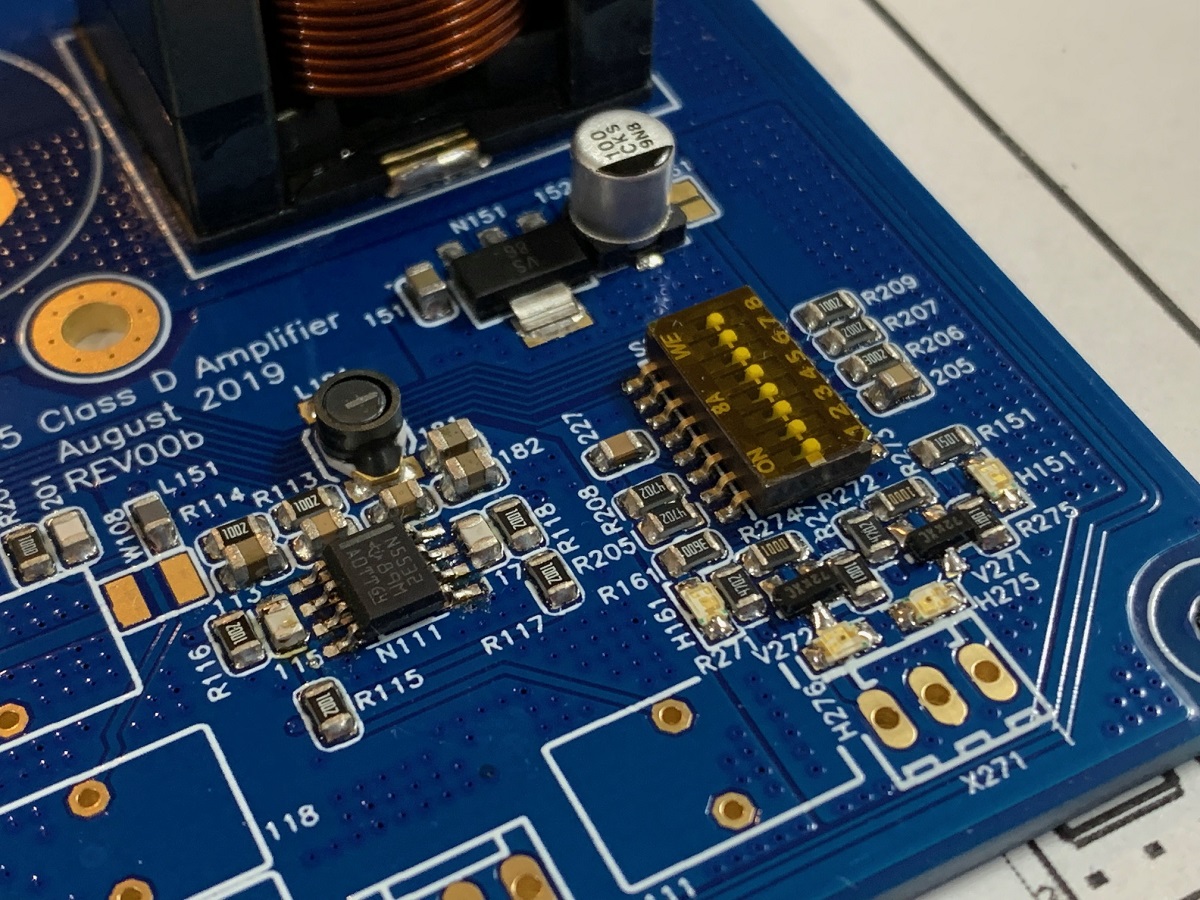
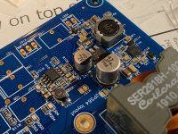
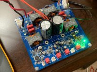
Power on test is encouraging. All power supply sub rails working to make 15v, 12v, 3.3v from 51v input. Working on configuring correct wire jumpers on input opamp stage and mode selector for stereo BTL. I got music to play with SE input but get error light when using balanced input. The reset button works too. So getting closer.
There is error on some silk screen labels of Wxxx solder jumper pads. Also error on N151 3.3v LDO pins. Need to isolate pin 4 from pad as that is output but board has it as GND.
There is error on some silk screen labels of Wxxx solder jumper pads. Also error on N151 3.3v LDO pins. Need to isolate pin 4 from pad as that is output but board has it as GND.
Attachments
Isn't Sn42Bi58 a bit on the low side for a high power system? The melting point is at 138°C and due to the Bismuth it cracks pretty easily when loaded with some mechanical force.
The OTE trip point of the TPA32XX is well above melting temp, hmm.
Just saying.
The I-Extruder is a nice tip, thanks for that.
The OTE trip point of the TPA32XX is well above melting temp, hmm.
Just saying.
The I-Extruder is a nice tip, thanks for that.
Last edited:
You are right, I wish I switched to the PbSn but was lazy as this was already loaded up. I have gone over the TPA3255 pins with some PbSn paste and reflowed with a solder iron tip. Hopefully that keeps the pins from debonding under power.
I am trying to figure out what’s keeping the amp from running with balanced input and stereo BTL output.
I am trying to figure out what’s keeping the amp from running with balanced input and stereo BTL output.
- Home
- Group Buys
- TPA3255 Reference Design Class D Amp GB