We will provide a single-click to order shopping cart for the BOM from Mouser. Vacuphile has offered to assemble the shopping cart as a Beta tester. Kay Pirinha has also offered to be a Beta tester.
Nice! I think we all know it's not a cheap project (you have ebay for that), but that amp is intend to play for years so lets go on...
More than just last for years - features are now available that are not to be found on the cheap Chinese amps, and the performance should be better with good components and careful layout. Parts cost probably $80 to $120 depending on quantity. We won’t know until Vacuphile makes the shopping cart on Mouser.
You can adjust the input gain by varying the resistors on the analog input stage balanced pre section - although not sure how much range there is to do that without it affecting other aspects. It is unity gain at present. This amp has 22dB gain and if people want to drive it to clip with normal line level signals, an 8dB to 10dB preamp for volume control would be useful.
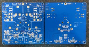
The PCBs are suposed to arrive today.
The PCBs are suposed to arrive today.
Assuming the beginner practices solder paste and hot air / hot plate soldering technique on test board first and can successfully solder 0603 parts and larger electrolytic SMT caps, maybe 4-6 hours. The self “training” on test boards is probably 2-3hrs.
You need a $40 hot air SMT rework tool. A $10 skillet, a $10 dorm room hot plate, $15 IR thermometer, $15 syringe of solder paste, $20 SMT tweezers, $10 magnifying flip up goggles, liquid flux $10, solder braid $3, and regular soldering iron. Those are the bare minimum tools and supplies needed to solder this yourself.
More tips here:
Making balanced output from single end
This is how I soldered this board:
Last edited:
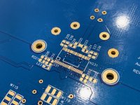
Hmm, soldering big inductors on 2mm 2oz. copper pcb might be a challenge with just using a hot air gun. You'd probably need to preheat the pcb as well. (Or solder them with an iron and leave out the mounting tab)
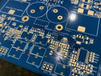
Btw. You have Conformité Européenne documents available, as indicated by "CE" on the PCB?
Btw. You have Conformité Européenne documents available, as indicated by "CE" on the PCB?
Last edited:
So quite achievable once you have the hang of it but reasonable challenging to begin with. I see you can buy some practice boards on ebay....
P.S. xrk I remember well the dead bug3116 you built back many thousands of posts ago. That was an exciting amplifier back then. As much as the 3116 excited me back then the 3255 is really exciting!
P.S. xrk I remember well the dead bug3116 you built back many thousands of posts ago. That was an exciting amplifier back then. As much as the 3116 excited me back then the 3255 is really exciting!
Last edited:
Hi Blossom,
Yes, going back on memory lane I do recall those were fun and exciting times. My eyes were also much younger then. Nowadays i have the privilege of having masters of layout like JPS64 and Jhofland help me put these amp designs to reality and the availability of low cost PCB fab. So no more dead bug SMT amps for me.
I still like making the occasional home etched PCB when there is a reasonably simple circuit and I am in a rush to try it. I do the manual layout using PowerPoint drawings for xerox transfer mask etchings.
The CE label is just that, a label on the PCB. For the device to be CE certified for commercial sales, it has to go through CE testing of course.
CE is a self certification, you need to be able to provide a document that details how the product complies with relevant CE sections if challenged. The easiest way to do this would be to use a 3rd party company to do the testing and provide an analysis document, however, this isn't strictly necessary and if you can prove it was designed to comply with CE, this is enough.
Pretty sure the only relevant one for a PCB (particularly a bare PCB) that doesn't deal with AC is RoHS anyway.

For now, I can only offer a bare PCB. Price will be $37ea and pre-orders will be taken once we verify the circuit works. It’s not a bad project to learn SMT soldering skills on. Watch some YouTube videos on solder paste hot skillet and hot air soldering. Use skillet on bottom to preheat board to 130C. Apply hot air from above to region of interest to liquify the paste and effect the solder. Work section by section. The 130C heat from bottom won’t hurt the parts and you do the TPA last as it is on the bottom side. It has to be done with just hot air (or traditional solder iron) as the top side will already have been populated.
TPA3255 Reference Design GB List
Name - Number of boards - Country
For example:
xrk971 - 2 boards - USA
TPA3255 Reference Design GB List
Name - Number of boards - Country
For example:
xrk971 - 2 boards - USA
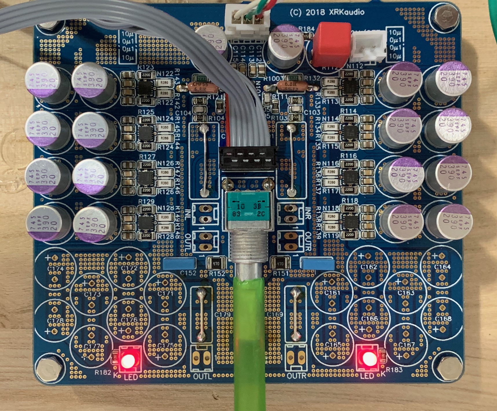
Have you included the clip indicator in the board?
Yes, there is also fault/error indicator LED. It’s all on the schematic, version 00b:
https://www.diyaudio.com/forums/att...rence-design-class-amp-gb-tpa3255_sch_00b-pdf
Last edited:
Nice to see you take a trip 'back' to where the hobby seem to have started. Groundplane looks much better to me in later design, I would however make the point connecting power and analog\input ground inside tpachip only, remove all connections on pcb. Multiple 'stars' do not function reference-like I think, although doctorm could probably tell you how it will show in measurements exactly.
- Home
- Group Buys
- TPA3255 Reference Design Class D Amp GB