I should add that proper earth grounding procedures are necessary to eliminate hum as always. The SMPS800RE has an EIC shell with earth ground but it leads to a standoff pad to chassis ground. I had to install a ground wire from the earth ground (isolated from -ve output) to the PE pin on the amp in order to elimminate a slight hum in one channel. But all is good now.
That bring up a good point. When this is put in a proper case, the PCB should be grounded at the PE (physical earth/earth ground) point, or screws on either side of the chip? The way the HS is configured now, it is isolated from chip, but the screws are not. So, if I were to use the amp enclosure as the HS (my first time ever), the chip obviously still needs to isolated (non-conductive) with enclosure. In that case, the PCB would be grounded by the 2 screws by default. I'm sure I've got this right, but just wanted to run it by you. I know it pretty basic. ")
I mentioned this earlier and also in the instructions included with the amp.
The chip thermal pad is tied to 0v clean analog ground and the heatsink bolt holes are tied to the same 0v analog clean ground. The chassis should be connected to the single Faston at the back called PE. It is tied to 0v clean ground via an NTC and 22nF film cap as a ground loop breaker. The NTC provides about 10ohms of ground loop breakage while becoming 0.5ohms if the need arises due to a major fault for safety. The 22nF cap suppresses RFI that might be going through the ground loop breaker. The remaining 4 PCB mounting hole pads are electrically isolated from any ground on the PCB.
The 0v analog clean ground must not touch chassis earth (dirty) ground. Hence, use an insulator on the heatsink. Either a silicone pad at thermal conductor block between heatsink chassis and block. Or use ceramic spacer with paste between chip thermal pad and heatsink and nylon shoulder washers on the M3 bolt that clamps the heatsink. Either way, check to make sure chassis is not connected to 0v analog clean ground. I should provide a hook up grounding diagram.
Last edited:
No problem. It needs repeating since it was so long ago that I mentioned it. I think I looked into using 10mm wide x 5mm thick would be perfect. Cut a bar about 50mm long and drill and tap two M3 holes 36mm apart on the 10mm wide face. Mount that to the PCB and TPA3255 chip as usual. Now get some 1mm silicone thermal spacer pad sheet material and insulate the 50mm x 10mm bar from the chassis. The silicone will compress. Find ~7mm standoffs (adjust with shims etc) and bolt the amp board to the chassis clamping the silicone between the 50mm x 10mm aluminum block. Be careful not to over clamp the TPA3155 chip.
1pc 6061 T6 Aluminum Alloy Flat Bar 5mm x 10mm x 500mm #EE-B8 GY | eBay
5 Pieces Durable Silicone Thermal Pad Thick 1mm for CPU GPU Heatsink new US | eBay
1pc 6061 T6 Aluminum Alloy Flat Bar 5mm x 10mm x 500mm #EE-B8 GY | eBay
5 Pieces Durable Silicone Thermal Pad Thick 1mm for CPU GPU Heatsink new US | eBay
Hi Folks, due to popular demand. The TPA3255 amp spare units have sold out! Thank you all for your patronage!
If you are interested in participating in another GB, please add your name and number of units to the interest list below. I will need at least 15 units of committment. The pricing has increased to $259 ea as the actual costs with testing, providing connectors, ESD safe packaging, boxes, and shipping the PCBs to the assembly house and then shipping the built units back are all real costs that I did not properly account for in GB 1. It is a superb sounding amp though, and tough to beat for a 4ohm capable amp with hundreds of watts of power.
GB 2 Interest List, we need 15 units
JohnDoe / 1 unit / USA
Last edited:
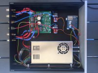
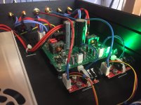
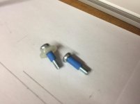
I used the PCB to make a template for drilling the chassis, and then a 10x10 aluminium bar with a TO220 ceramic insulator for heat transfer to the base plate. I got the height of the PCB right by adjusting the make up of the mounting bolts, ending up with 1 washer, 1 nut and a 10mm hex spacer. Improvised some insulated screws for the heatsink mounting by adding some heat shrink and the only nylon washers I had to hand which were far too big to drill the PCB for.
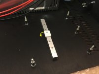
The ceramic insulator must be rotated 90deg to the orientation shown in the photo (see the arrow). The end of the insulator with the hole should hang over the edge of the bar towards the "input" end of the PCB otherwise it will rest on the SMD capacitors rather than the IC. It needs to be placed accurately as there is not much clearance to the surrounding components. I added a very thin layer of "Arctic MX-4" non conductive heatsink compound between the IC / Ceramic insulator / Alu bar / chassis.
I'm really pleased how this has come out - great work xrk971 and all involved.
Attachments
Beautiful job, Jrosser! Very impressive looking and so neat and tidy!
You are certainly not going to have any loss of impedance between the amp and the speaker output posts with 8x 14ga wires per speaker!
What does that Arduino do?
How is the MW PSU working out for you? Does the fan kick in and out t the noise and issue?
Congrats on one the nicest builds for a Class D amp I have seen.
Last edited:
Just to clarify the grounding of the thermal transfer block from the chip to the chassis: The block itself can be bolted to the thermal pad of the TPA3255 directly. No shoulder washers or insulation or ceramic pad needed. However, the thermal block needs to be electrically insulated from the chassis. This can be done with silicone sheet.
The way you did it works too - isolate the thermal block from the PCB 0v and TPA3255 thermal pad. Then the thermal block can be in electrical contact with the chassis.
The nice thing about the silicone thermal spacer is it allows some give so that the height differences are accommodated somewhat.
The way you did it works too - isolate the thermal block from the PCB 0v and TPA3255 thermal pad. Then the thermal block can be in electrical contact with the chassis.
The nice thing about the silicone thermal spacer is it allows some give so that the height differences are accommodated somewhat.
Beautiful job, Jrosser! Very impressive looking and so neat and tidy!
Hi xrk971 - thank-you for your kind words! I've really enjoyed putting this together, probably taken about 30hrs with all the metalwork.
You are certainly not going to have any loss of impedance between the amp and the speaker output posts with 8x 14ga wires per speaker!
The speaker wire isn't quite that excessive
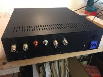
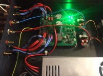
I've used speakons on the back panel as well as 4mm posts, so the mini-fits go to the speakon outlets and the fastons to the binding posts, it's 16ga silicone wire which crimps beautifully. Doubling up the wire and adding the heat-shrink rings makes it 'set' into place and stay put which has really helped the tidiness.What does that Arduino do?
The Arduino is connected to the front panel switch (momentary) and LED, plus it drives the "RC" input on the Meanwell SMPS so the 48v is on/off controlled by the software. I want to add an opto isolator input for remote start, and may also hook up the fault/clip header of the amp board to flash the front panel LED. It's really there as a bit of forward planning....
How is the MW PSU working out for you? Does the fan kick in and out t the noise and issue?
The Meanwell PSU is working out fine so far but i've only had it running for a few hours so it's a bit early to say. I've had to remove the fan completely - the datasheet says it is speed controlled but it's very loud right from first power on. For normal domestic duties i'll probably be OK without it. The SMPS is this Mean Well SPV-300-48 chosen for the remote on/off logic input.
Congrats on one the nicest builds for a Class D amp I have seen.
Cheers! Now I need to go hook it up to my Jamo Concert 8 which do their best with a powerful amp, this should be just the job.
Oh I did not see the Speakons - black on black! I like your Speakon PowerCon too. I night some and have been looking for an amp to use it in.
I also use 16ga silicone wire for speaker internal connects now too. Great stuff.
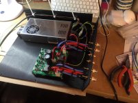
Please double check your left and right inputs. This amp board right input is on left side and output on right side. It crosses over since TPA3255 is on underside. Your photo shows left driving right and vice versa. Just swap the output wires from the THAT1646 to the amp.
I also use 16ga silicone wire for speaker internal connects now too. Great stuff.
Please double check your left and right inputs. This amp board right input is on left side and output on right side. It crosses over since TPA3255 is on underside. Your photo shows left driving right and vice versa. Just swap the output wires from the THAT1646 to the amp.
Last edited:
@X, I'm currently thinking about a suitable enclosure and what type of inputs I should use to make the amp a bit more flexible. Since I'd like the amp to be as versatile as possible, I was going to fix XLR inputs on the back panel, since they conveniently connect to the balanced inputs the amp was designed for.
My question is.... should I want to drive it from a single-ended pre, say the Yarra, are there any issues with simply using standard RCA to XLR cables to drive it directly, and for-going the THAT devices? I could do both types of inputs, and use a switch to select between the two as well.
On another related topic... should speaker protection be used like your SS DC Protection Circuit. Thoughts?
- Home
- Group Buys
- TPA3255 Reference Design Class D Amp GB