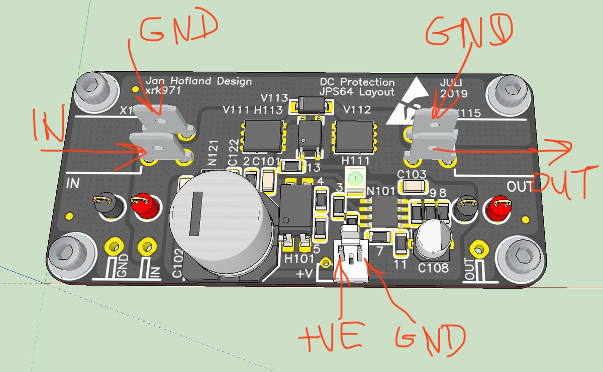
Those other pins are optional test points and flying lead connection pads. Simply use your DMM in continuity mode to find out which is which.
Great - thanks, X.
Andy
If I'm providing a separate supply, then it has both positive and ground, and its ground is not the same as the amplifier's ground. Hence, my question about whether those two grounds (board supply ground and audio ground) are common on the board.
Could you just connect the GND of your separate PSU to the existing GND of your amp? Then the two GNDs would be the same and all is good.
But... taking this thought one step further: what if none of the speaker outputs are connected to GND, for example in a bridged amplifier? While the DC across the terminals might be fine, there may be a bit of DC from each terminal to the PSU GND. If the DC protection board senses the DC from the speaker output relative to the PSU GND, it will turn off the speakers, although there is no (significant) DC across the speaker terminals. Soooo... one could add a separate PSU for the DC protect board (for example a cheap SMPS or wall wart), and connect the "GND" of this separate PSU to one of the speaker output terminals? The DC protect board would then only sense the voltage across the speaker terminals, not the terminals relative to the GND of the main PSU.
Would that work? Would it work well? Any issues with this?
Actually, the voltage regulator can handle 150v. However, make sure the voltage drop x 4mA dissipation isn’t too high. 60v - 15v is 45v x 4mA is 180mW. That should be fine. You can use the on board 60v supply.
That's perfect, thanks!
Could you just connect the GND of your separate PSU to the existing GND of your amp? Then the two GNDs would be the same and all is good.
But... taking this thought one step further: what if none of the speaker outputs are connected to GND, for example in a bridged amplifier? While the DC across the terminals might be fine, there may be a bit of DC from each terminal to the PSU GND. If the DC protection board senses the DC from the speaker output relative to the PSU GND, it will turn off the speakers, although there is no (significant) DC across the speaker terminals. Soooo... one could add a separate PSU for the DC protect board (for example a cheap SMPS or wall wart), and connect the "GND" of this separate PSU to one of the speaker output terminals? The DC protect board would then only sense the voltage across the speaker terminals, not the terminals relative to the GND of the main PSU.
Would that work? Would it work well? Any issues with this?
This was actually the change proposed for version 2 of this circuit. The PSU to actuate the SSR could be from the amp itself or another PSU, and the ground of the actuation circuit would be isolated from the amp return. When the second batch sells out maybe we can go to version 2. This will handle BTL amps and will have a remote trigger for instant shutoff when the main PSU is switched off. But getting a new production with a new circuit and BOM is quite a challenge.
This was actually the change proposed for version 2 of this circuit
Yes, I remember that discussion.
I am just wondering if my idea would work.
The current version of the SSR connects the aux supply - (GND) and the AMP low side, also GND. The offset is sensed between AMP high side and AMP low side (GND). Whether the SSR power supply is derived from the amplifier power or a separate supply does not change this. Using this version with bridge tied outputs works if, and only if, there is no offset from zero volts on the high side outputs with no input signal.
The current version of the SSR connects the aux supply - (GND) and the AMP low side, also GND. The offset is sensed between AMP high side and AMP low side (GND). Whether the SSR power supply is derived from the amplifier power or a separate supply does not change this. Using this version with bridge tied outputs works if, and only if, there is no offset from zero volts on the high side outputs with no input signal.
Yes, sure, but... what if I have a floating helper PSU for the SSR, with the "low" end of the PSU connected to one of the speaker outputs? The SSR would not know that it is not referenced to the main amplifier GND. Instead, I guess the SSR would just sense the DC relative to the "low" end of the helper PSU. Right?
That is right, kind of. If that floating supply is truly floating then there is no closed current loop between the amplifier output and the SSR circuit. The the sensing part of the circuit is an RC lowpass network connected to the IR LED in an optocoupler and then to the amplifier low side to form a closed sensing loop. That low side is connected to the - side of the circuit power.
That is right, kind of. If that floating supply is truly floating...
What do you mean by this? How would a floating supply not be "floating"? For instance this: RS-15-24 MEAN WELL | Mouser Schweiz
The mean well is an isolated supply, meaning the output is isolated from the input (line/source) and thus the output voltage can be considered floated from other voltages produced from that source. Those outputs will not longer be floating if they are electrically connected to another DC source, thus the mean well’s output will somehow be referenced to the other DC source.
You can check (to certain level of confidence) if source is floating from another by measuring the voltage across the two supplies.
You can check (to certain level of confidence) if source is floating from another by measuring the voltage across the two supplies.
Hi X,
Can you please confirm that you used a Wurth 2-pin male connector on the PCB (for power). I'm assuming it is Wurth because it's physically slightly different from the Molex 2-pin connectors specified for the AN boards (the plastic 'lock' behind the pins is longer).
If you could also tell me the Mouser part number, that would help me find the matching female connector in the Mouser catalogue.
Thanks,
Andy
Hi Andy,
It’s definitely Molex KK, although Wurth makes Molex compatible stuff sometimes.
Here is the PCB male pin header Mouser part:
538-22-23-2023
Here is the matching plug connector:
538-22-01-3027
Here is the crimp female terminal that goes in the socket:
538-08-50-0032
It’s definitely Molex KK, although Wurth makes Molex compatible stuff sometimes.
Here is the PCB male pin header Mouser part:
538-22-23-2023
Here is the matching plug connector:
538-22-01-3027
Here is the crimp female terminal that goes in the socket:
538-08-50-0032
Hi Andy,
It’s definitely Molex KK, although Wurth makes Molex compatible stuff sometimes.
Here is the PCB male pin header Mouser part:
538-22-23-2023
Here is the matching plug connector:
538-22-01-3027
Here is the crimp female terminal that goes into the socket:
538-08-50-0032
Thanks, X.
Better crimp terminals, I suggest, are: 538-39-00-0039.
(This is what was specified in the AN BoM.)
Andy
Thank you, Stretchneck for your patronage and confidence! These RTR SSRs are great little units that are easy to use. Very much a “set it and forget it” type of thing. You won’t know they are there other than you won’t hear a start up thump and you won’t hear the sound of a voice coil flying out of the driver or smell one burning up. ")
- Home
- Group Buys
- Ready-to-Run (RTR) SSR DC Speaker Protection and Delay GB