Hi Voxx,
It’s good that you ask. This is actually kind of tricky and it seems simple enough but I have had problems sometimes.
For your question:
Trafo secondaries are always “hot”. Do you mean the primaries that connect to mains are hot and neutral?
If there are 3 wires on secondaries it would mean that it is center tapped?
A photo or schematic diagram would be helpful.
In any case, if you can use a DMM and measure 15vac from one pair of the secondaries, (any two wires), connect those to the AC input of the small PSU board (pins 1 and 3 of J2) and connect the middle ground pin to the ground of your amp’s main PSU for reference only if using the same secondary from your main power transformer as the amp.
If a shared trafo is used for the SSR then connect pin 2 to one of the AC secondaries of the trafo to form a ground reference for the small PSU board.
Load D1 and D2 only if using separate dedicated trafo, else do not populate them if using common trafo secondary as main amp.
Last edited:
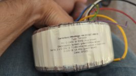
Thanks ") I was referring to my transformer which has two windings (I believe this is what its called ) - one output 2x 35 (4 wires ) ac, another 15 AC (2 wires).
I was referring to my transformer which has two windings (I believe this is what its called ) - one output 2x 35 (4 wires ) ac, another 15 AC (2 wires).
See the image attached.
I ll have to remove D1 D2 then
I was referring to my transformer which has two windings (I believe this is what its called ) - one output 2x 35 (4 wires ) ac, another 15 AC (2 wires).See the image attached.
I ll have to remove D1 D2 then
Attachments
4 since dedicated secondaries. But will work with only two if you want to save on diodes.
Clarification from Jhofland:
“If your AC source is 2 wire (a single secondary) then load D1 and D2 to get full wave rectification and don't connect COM input. If your AC source is a center tapped (3 wire) secondary then do not load D1 and D2.”
Clarification from Jhofland:
“If your AC source is 2 wire (a single secondary) then load D1 and D2 to get full wave rectification and don't connect COM input. If your AC source is a center tapped (3 wire) secondary then do not load D1 and D2.”
When I last checked this thread for answers a few days ago I think the last post published was about #941. Since I'm pondering ways to power the SSR boards on another mosfet amp I'm building, I checked back late last night and there was the info I needed; power the low cap quick shutdown board from a single 15v raw AC secondary. This begs a question in my case though. 15v ac rectified is about 21vdc. Can I now use a 22uf 35v cap safely instead of a 50v rated cap? All I have is 4.7uf & 10uf at 50v.
Thanks for the clarifications, X!
Jim
Thanks for the clarifications, X!
Jim
It has been a while since the last post, but maybe someone can answer my question about the TVS diode protecting the MOSFETs. Why do they have the same voltage rating as the MOSFET ? The BSC0402NSAT is rated for 150V, but a TVS like the SMAJ150CA with Vr=150V would not break down before 167V and clamping voltage is even 243V. So how can the diode protect the MOSFET ?
Hi Tojoko
I believe he sells them here:
Ready-to-Run (RTR) SSR DC Speaker Protection and Delay
Trigon
I believe he sells them here:
Ready-to-Run (RTR) SSR DC Speaker Protection and Delay
Trigon
- Home
- Group Buys
- Ready-to-Run (RTR) SSR DC Speaker Protection and Delay GB