I’m working on a modified design for use in the upcoming Aurum-X 300w lateral FET Class AB amp. We found a MOSFET that can take 250v, 64A and 17.5mohm RDSon. We also are designing a simple voltage regulator to drop the 70v rail to 15v. It will be interesting to see how it works relative to the current model.
Hi Meanie,
Great news to hear that they arrived safely in Singapore.
This is everyone:
I think I mixed up an order and somebody received an extra set of SSR’s. I only know because someone said that they only got 2 when they ordered 4.")
I know how many were tested and sent out in total.
No worries - the mistake is my gift to you.
Great news to hear that they arrived safely in Singapore.
This is everyone:
I think I mixed up an order and somebody received an extra set of SSR’s. I only know because someone said that they only got 2 when they ordered 4.
I know how many were tested and sent out in total.
No worries - the mistake is my gift to you.


Hi Xrk971
I was looking for a DC speaker protection, to be used on a 125W 8 ohm, class AB, but your RTR SSR board only handles 100W. Is it better to wait for your new board ready for the Aurum-X or the first one is ok ?
Regards
That is going to be built on-board the Aurum-X so no standalone board is currently planned anytime in the near future.
125w into 8ohms is 89Vpp vs 80Vpp for 100w. Let’s see what Jhofland says but I believe it should be fine.
Just checked and Jhofland reminded me we are using 100v rated MOSFET so you are fine. Can actually go to 150w but that’s right at the edge of 156w max voltage.
Last edited:
Just checked and Jhofland reminded me we are using 100v rated MOSFET
I was just thinking about OTL tube amps... what happens if **** hits the fan and we end up with 150 or 200 VDC before the DC protect? I guess the DC protection board might die under these circumstances; but will it pass the DC, or will it still keep the DC away from the speaker?
I haven't heard anything from my boards... is there a way to track the shipping?
You should have received an email with tracking. I’ll check for you.
Thanks, received the email. Shipping looks okay.
Any thoughts about this? I was just thinking about OTL tube amps... what happens if **** hits the fan and we end up with 150 or 200 VDC before the DC protect? I guess the DC protection board might die under these circumstances; but will it pass the DC, or will it still keep the DC away from the speaker?
Is the ground for that power-in ground connected to the audio ground? If I have a separate power supply for the speaker protection module, I want to make sure it doesn't share the same ground.4. Also can it be powered from a separate supply - that is , it does not need to be referenced to the amp supply for the amp it is protecting.
That's correct, a 19v or 24v volt supply from a wall wart would be fine.
On the board, the Ground is shared. However, it is simply a pass-thru for the speaker. You can simply wire the amp -ve (return) directy to the speaker output binding post, or in some cases, people wire the speaker -ve directly right back to the star GND hub on their PSU, bypassing the RTR SSR completely.
Last edited:
Yes, I plan to wire the speaker ground directly to the output binding post. My concern, however, is with the board's power supply ground. My amplifier rails are ±60VDC, which is too much for the speaker protection module (which apparently doesn't want more than +50VDC). Therefore, I need a separate supply for the board.On the board, the Ground is shared. However, it is simply a pass-thru for the speaker. You can simply wire the amp -ve (return) directy to the speaker output binding post, or in some cases, people wire the speaker -ve directly right back to the star GND hub on their PSU, bypassing the RTR SSR completely.
If I'm providing a separate supply, then it has both positive and ground, and its ground is not the same as the amplifier's ground. Hence, my question about whether those two grounds (board supply ground and audio ground) are common on the board.
While I'm at it, I assume that supply to power the board needs to be 19V DC. I've been using cheap Chinese speaker protection modules, and I'm starting to suspect they're too cheap to trust. Hence my desire to use these boards instead. I was supplying them with 12VAC, but I can also do 24VAC with the same transformer. If I need ≥19VDC instead, then I may forego that transformer and use something like MEAN WELL IRM-01-24 to convert from 115VAC directly to 24VDC. Does that make sense?
Thanks in advance for your feedback.
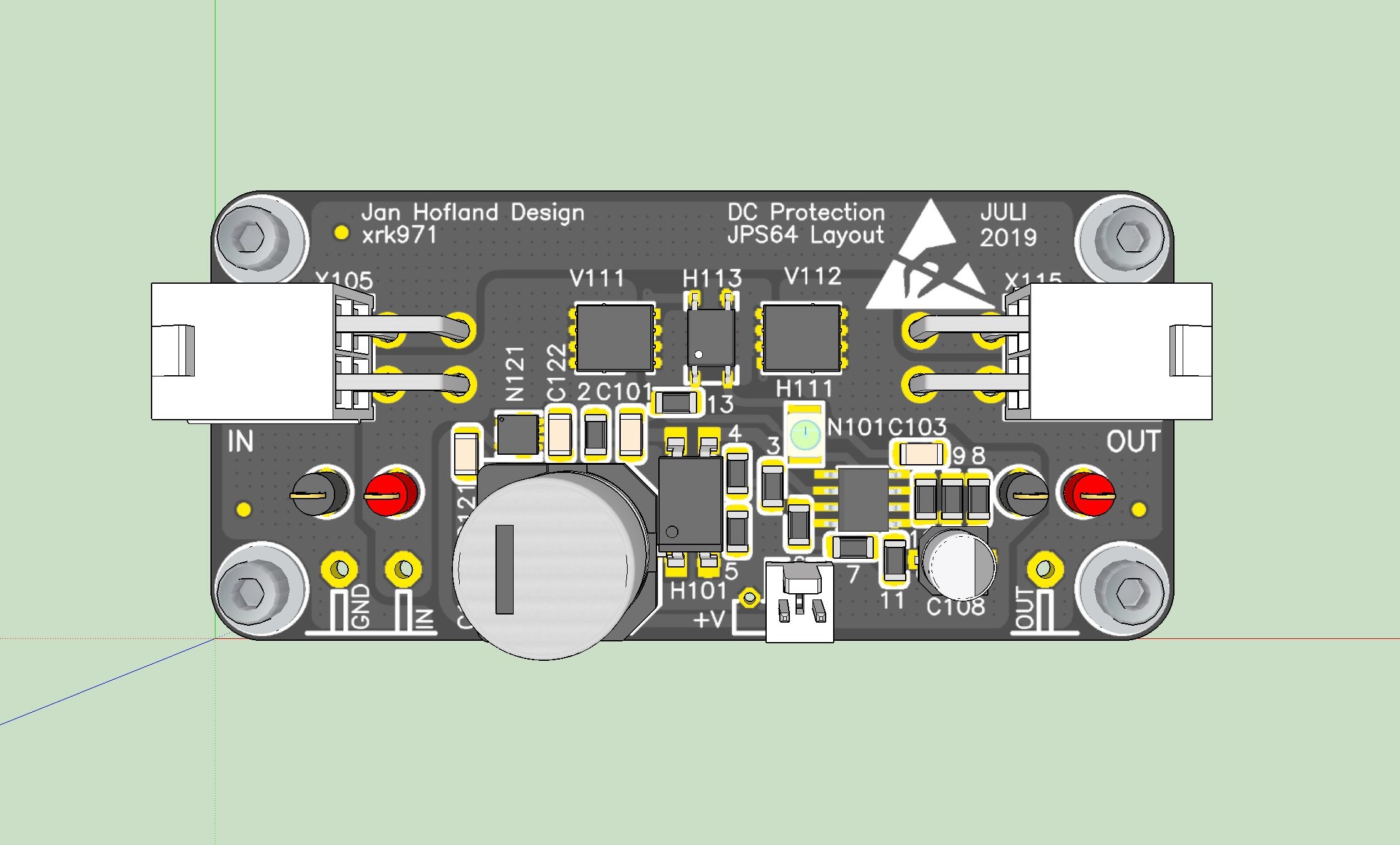
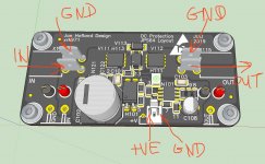
No, 2 wires are +ve and 2 are GND. The top 2 are GND and bottom 2 are +ve from amp on left and to the speaker on right side. Just look at the traces. They are paralleled for more current.
Hi X,
Sorry, I'm afraid I have some difficulties with the schematic in your post #364.
OK, the top 2 holes on X105 (input) and X115 (output) are Ground - so I can use the bottom 2 holes:
* on X105 to take a spade terminal for the AN PCB spkr out
* and on X115 for a spade terminal which will connect to the +ve spkr terminal.
And I take Ground straight from the AN PCB to the -ve spkr terminal.
Correct?
So I don't need to use the following:
* the red & grey 'things' underneath X105 & X115
* or the gold-flashed holes below them.
Correct?
Also, the 2-pin Molex connector down the bottom is to provide +ve DC and Ground to the SSR? The +ve DC is the pin on the left?
Correct?
(I ask this because the '+V' is actually printed next to a 3rd hole - which is unused.)
Thanks,
Andy
- Home
- Group Buys
- Ready-to-Run (RTR) SSR DC Speaker Protection and Delay GB