Just a heads up for RTR SSR fans...
Jhofland, JPS64, and I are designing a new SSR based AC mains soft start module. It will be DIY friendly with only a single (maybe two) SMT part(s). Should be easy to build and easy to use. Just connect some spades in from EIC and trafo primaries out and you are done. Another 1 minute installation job.")
Jhofland, JPS64, and I are designing a new SSR based AC mains soft start module. It will be DIY friendly with only a single (maybe two) SMT part(s). Should be easy to build and easy to use. Just connect some spades in from EIC and trafo primaries out and you are done. Another 1 minute installation job.
GB #2 List
20 units so far. Need minimum 40 to manufacture.
xrk971 4 units USA
tcpip 6 units USA
mbrennwa 6 units Switzerland
Andyr 4 units AUS
20 units so far. Need minimum 40 to manufacture.
SunShade 8 units Italy
GB #2 List
20 units so far. Need minimum 40 to manufacture.
GB #2 List
26 units total. We need 40 minimum for GB to proceed to manufacturing.
xrk971 4 units USA
tcpip 6 units USA
mbrennwa 6 units Switzerland
Andyr 4 units AUS
Sunshade 6 units ITALY
26 units total. We need 40 minimum for GB to proceed to manufacturing.
SunShade seems to have said 8 units and your summarised list puts 6 against his name. If this is a slip-up, maybe you should fix it?26 units total. We need 40 minimum for GB to proceed to manufacturing.
GB #2
Yes, my mistake. Thanks, tcpip.
Total 28 units.
Yes, my mistake. Thanks, tcpip.
xrk971 4 units USA
tcpip 6 units USA
mbrennwa 6 units Switzerland
Andyr 4 units AUS
Sunshade 8 units ITALY
Total 28 units.
GB Status Update
32 Units total.
@mpa: thanks for letting me know they arrived and are working well.
xrk971 4 units USA
tcpip 6 units USA
mbrennwa 6 units Switzerland
Andyr 4 units AUS
Sunshade 8 units ITALY
Schlomoff 4 units FR
32 Units total.
@mpa: thanks for letting me know they arrived and are working well.
GB Status Update
xrk971 4 units USA
tcpip 6 units USA
mbrennwa 6 units Switzerland
Andyr 4 units AUS
Sunshade 8 units ITALY
Schlomoff 4 units FR
jwjarch 4 units USA
36 Units total.
X, regarding the soft start boards, if using the SLB boards does the soft start add any benefit or is it redundant?
xrk971 4 units USA
tcpip 6 units USA
mbrennwa 6 units Switzerland
Andyr 4 units AUS
Sunshade 8 units ITALY
Schlomoff 4 units FR
jwjarch 4 units USA
36 Units total.
X, regarding the soft start boards, if using the SLB boards does the soft start add any benefit or is it redundant?
Requires > +19vdc power supply (can use +ve rail from your amp) and internally regulated to 15v
Is it possible to make it work with a 15 VDC power supply?
I am thinking to use the protection boards for a Borbely headphone amp that runs off +/- 15 VDC PSU.
I think so, just bypass the votage regulator and let the +V drive teh circuit directly. The operation of the regulator might be just that if the voltage is less than 3 above 15v, it just passes it through with some set delta, probably 0.6v drop for going through a pass-transistor. In which case, 14.4v should still be enough for the circuit to work but note that the performance of the shutoff will depend on how clean your PSU is. I will ask Jhofland to give his opinion - which would be the more accurate assessment than mine.
I'd like more information on the soft start SSR project. Will the new project incorporate both the DC protection and soft start on the same card?
Always wanted to make soft start circuits based on this app note http://www.mosaic-industries.com/em...rola-an1542-active-inrush-current-limiter.pdf
Always wanted to make soft start circuits based on this app note http://www.mosaic-industries.com/em...rola-an1542-active-inrush-current-limiter.pdf
We are working on a soft start now. The SSR protection is a separate circuit - as the soft start is a totally different functionality - it is tied to the AC mains. You don't want your speaker level signals anywhere near that. There are two versions, a simple one for a single trafo with two primaries and a double one that handles two independent trafos, 4 primaries total. They will use SSR's to bypass (short out) a set of 4 parallel 100ohm resistors that will be 25ohm load for the soft start. There will be a programmable time delay 0.5s, 1s, 2 sec period where the SSR will then shunt across the resistors to allow full current to flow to the trafos. The double one will have an added feature of a SCR to permit remote turn on/off via a logic level. We were almost ready to make prototype boards when jhofland found some more optimizations on the circuits so it was back to the drawing board. Maybe another 2-3 days and we can release the schematic and 3d renders.
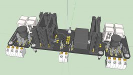
In the same philosophy as the SSR's, it will be very easy to connect and use. Basically connect 3 wires from your IEC capsule (L, N, E) on one end, then connect your trafo primaries on the other end (AC1, AC1', AC2, AC2'). There will be a way to select 115VAC or 230VAC mains (parallel or series) connections on the primaries.
Hope that answers some of your questions.
Some teaser pix (this is the dual trafo version):

It is meant to mount on the amp front panel (where the trafo normally resides) and has and indicator bi-color LED and remote power switch. You will have your choice of faston spades or screw terminal blocks. The single trafo one only has spades and no remote on/off capability.
In the same philosophy as the SSR's, it will be very easy to connect and use. Basically connect 3 wires from your IEC capsule (L, N, E) on one end, then connect your trafo primaries on the other end (AC1, AC1', AC2, AC2'). There will be a way to select 115VAC or 230VAC mains (parallel or series) connections on the primaries.
Hope that answers some of your questions.
Some teaser pix (this is the dual trafo version):
It is meant to mount on the amp front panel (where the trafo normally resides) and has and indicator bi-color LED and remote power switch. You will have your choice of faston spades or screw terminal blocks. The single trafo one only has spades and no remote on/off capability.
Attachments
Last edited:
Sorry about that, missed your question.
It is a totally separate matter. The soft start circuit is not to soft start the power into the amp (as a cap mx sometimes does as it ramps up to voltage). But a soft start is to slowly let curent into charging up the primaries on the power trafo when the power switch is turned on. This helps to reduce surge that often accompanies turning on a big power transformer. Sometimes it trips breakers or momentarily dims lighting. It also reduces the stress of charging up the primary bulk caps at turn-on.
I usually use an NTC like an 8D-20 (some use CL-60) in the primary of the trafo. This has about 8 to 10ohms resistance when cold, and as it heats up, becomes about 0.5ohms. The NTC doesn't provide soft start when it is hot and you power off and power back on before it cools.
...if using the SLB boards does the soft start add any benefit or is it redundant?
It is a totally separate matter. The soft start circuit is not to soft start the power into the amp (as a cap mx sometimes does as it ramps up to voltage). But a soft start is to slowly let curent into charging up the primaries on the power trafo when the power switch is turned on. This helps to reduce surge that often accompanies turning on a big power transformer. Sometimes it trips breakers or momentarily dims lighting. It also reduces the stress of charging up the primary bulk caps at turn-on.
I usually use an NTC like an 8D-20 (some use CL-60) in the primary of the trafo. This has about 8 to 10ohms resistance when cold, and as it heats up, becomes about 0.5ohms. The NTC doesn't provide soft start when it is hot and you power off and power back on before it cools.
I'd like more information on the soft start SSR project. Will the new project incorporate both the DC protection and soft start on the same card?
Always wanted to make soft start circuits based on this app note http://www.mosaic-industries.com/em...rola-an1542-active-inrush-current-limiter.pdf
I checked with jhofland and he advises against this - the circuit won't work as designed if the voltage drops to 15v.
However, if you used a very small DC-DC step up converter to get your 15v to say 20v, and fed that to the SSR (with a CLC filter in between), that would probably work fine.
Sorry about that, missed your question.
It is a totally separate matter. The soft start circuit is not to soft start the power into the amp (as a cap mx sometimes does as it ramps up to voltage). But a soft start is to slowly let curent into charging up the primaries on the power trafo when the power switch is turned on. This helps to reduce surge that often accompanies turning on a big power transformer. Sometimes it trips breakers or momentarily dims lighting. It also reduces the stress of charging up the primary bulk caps at turn-on.
I usually use an NTC like an 8D-20 (some use CL-60) in the primary of the trafo. This has about 8 to 10ohms resistance when cold, and as it heats up, becomes about 0.5ohms. The NTC doesn't provide soft start when it is hot and you power off and power back on before it cools.
Thanks for the reply X. That makes complete sense. I wasn’t separating the inrush to the transformer primaries from the PSU board itself, in my brain. Thanks for the explanation!
- Home
- Group Buys
- Ready-to-Run (RTR) SSR DC Speaker Protection and Delay GB