Thanks Hugh / X,
My plan wrt cooling. I have a length of square Aluminum, its in my shed at the moment but going from memory I think its around 3.5" - 4" square and about 30+ inches long. Material thickness, again from memory is ~ 3/16" - 1/4".
My thoughts thus far are cut it into ~ 15" lengths and mount the Mosfets and anything else on it with a Noctua fan connected to one end blowing internally, maybe use some cardboard and make a baffle to create a Venturi effect. If I am having heat dissipation issues with that setup then I will mount the actives internally and see how it goes.
Yes, ambient temperature creates a bit on an issue, part of the joys of Caribbean living!
All the best.
Andrew
Hi Andrewbee,
120w from a 2cm x 2cm patch of the MOSFET is a lot of heat flux. Generally, a copper pad and heat pipes are needed to effective transport that heat away fast enough. A plain aluminum wall may not be able to transport the heat away fast enough (unless water cooled). You should look for surplus CPU coolers designed for 120w+ CPU’s. Mid 2000’s Intel Pentium or Xeon CPU coolers usually are very good for this.
120w from a 2cm x 2cm patch of the MOSFET is a lot of heat flux. Generally, a copper pad and heat pipes are needed to effective transport that heat away fast enough. A plain aluminum wall may not be able to transport the heat away fast enough (unless water cooled). You should look for surplus CPU coolers designed for 120w+ CPU’s. Mid 2000’s Intel Pentium or Xeon CPU coolers usually are very good for this.
Yes, Andrew,
Thanks to X he gave the correct figures for a 4R Class A. Low impedance loads need very high quiescent current; 4.5A is correct and this will produce a 121W dissipation on EACH mosfet so you need lots of cooling, particularly if ambient temperature is high.
Should be very, very powerful!
Cheers,
Hugh
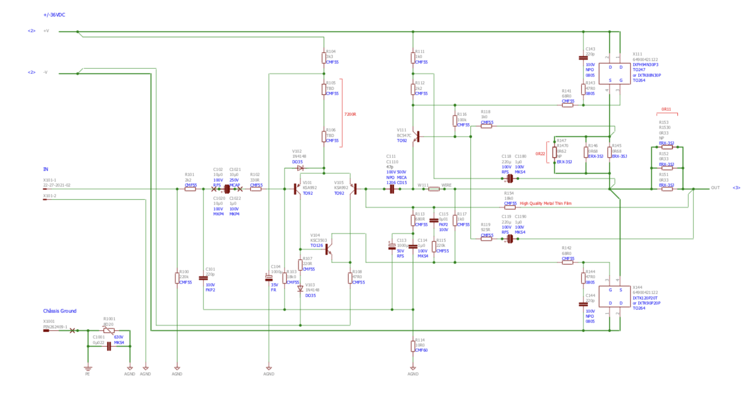
Which resisters do we change to achieve that bias?
Also the Aleph feedback sense resistors need to be set to approx 1/2 of the CCS sense resistor at 0.075ohms (or thereabouts). You can use 3 in parallel to achieve this as JPS64 provided 3 sets of pads. So 3x 0.22R 3w ERX Panasonic’s should do it for the sense at R151 to R153. And 3x 0.47R 3w ERX Panasonic at the R145-147 CCS should work.
The Dell FD841 is easy to find, inexpensive and proven to work well.
For example:
https://www.ebay.com/i/143334434046...9H-gx_SuEzSOIxqHLJc_qD485t5ncSvhoCwdkQAvD_BwE
Make sure that you get the version with a large rectangular copper pad and not diamond shaped one.
This looks ok too:
https://www.ebay.com/i/312033117943...yM7v0B-pcpiNl7gB-b6zAv-LfKbfjH4RoClFgQAvD_BwE
I think Vunce May have the details on the part number that distinguishes the two.
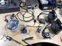
A little update on my progress. I have a working testing with 2 Corsair H60 All In One water coolers running off the 12v secondary and a small adjustable regulator PCB I have some stock of (Linear regulator PCB (LM317, LT1085, LM338, LT1083)). Each H60 pulls about 400ma for the pump and fan. Fans are adjusted using a simple 12v pwm controller, the same as I believe Vunce has used, though I have another interstesting one on order (DC 12 24V 48V 2-Way 4-Wire Computer PWM Temperature Control Fan Speed Controller 699934192570 | eBay).
Overall, I'm pretty satisfied with the sound level, the largest source of noise is the vibration from the pump (hosted in the actual cooling block). I will look to minimize this in construction by isolating the mounting of the cooling block from the rest of the chassis.
My next step is going to be actually starting to build one channel and testing the thermal performance of the H60s. I have all the parts ready to go, but was wondering what (if any) adjustments are needed to be made during or after construction. It looks like the two pots are part of the cap multiplier. I am assuming these are used to dial in the same voltage for both rails, any instructions on this? What voltage should we target? Where is the best spot and under what circumstances should we test this voltage (MOSFETs (dis)connected? under load? etc?)? Are there any other considerations / steps to take during construction and initial bring up?
Greg
Attachments
Nice setup there, Gtose! Looking forward to seeing how the liquid cooling works. If you upgrade those fans for he brown/beige colored Noctua's, there is a word of difference in fan noise reduction.
Regarding the pots on cap Mx, set it at midpoint to start off - it really does not change the output voltage a lot, maybe 1v to 2v, and I have found a good operating point is to adjust for about 3v of drop to get the lowest ripple.
It should be adjusted with the load in place, or the amp drawing 3A. You can measure the voltage at input to BJT and output of BJT of cap Mx and look on O-scope to see where the minimum tolerable ripple and minimum acceptable output voltage is. Less ripple (higher voltage drop) is less output voltage.
Cool setup gtose!
X pretty much covered start up, it’s a drama free amp to work with.
The tips I will add are:
-double and triple check you’re flying lead Molex connectors to make sure the wires are oriented correctly.
-Increase R308 from 100K to 150K
- you will have 1v or less adjustability with the trim pots on capMX, adjust for the lowest setting so both positive and negative are equal.
- Working voltage with a 32V transformer is between 37-38vdc.
Happy Building!!
One more thing, don’t forget to connect the BJT Molex connectors before firing it up under load! Magic smoke will come from one of the resistors that takes the brunt of the full current under load in absence of the outputs. Not a big deal in damage but very disconcerting to see smoke and flames. As this has happened to both Vunce and myself. I would say the chances of a stupid mistake like this is high, sans warning.

Depends on the current at high frequencies - usually not too high. The limitation is the current, and with 4ohm setup, 4.5A bias quiescent current limits the max current for a pure Class A amp like this. Test with a 4ohm amp that you have now. Put a 0.1ohm series shunt resistor and measure voltage across that at the typical SPL levels you need. The quiescent current needs to be 1.4x this amount. Or for 4.5A quiescent, you can support 3.2A peak current.
Last edited:
ABBB stuffed in a chassis
Hello fellow builders,
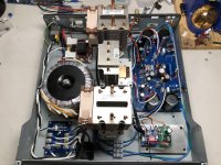
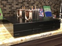
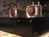
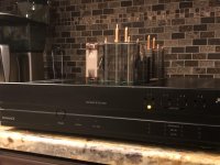
I thought I’d share a few pics of a fully functioning monoblock ABBB stuffed into a recycled chassis. The enclosure size is 17”x 17”x 3.5”, transformer is an Antek AN-6432, both BJT’s are mounted to the center cpu cooler(no fan required) flanked by the Mosfets mounted to independent coolers.
Since this was a recycled chassis, I will have to work on the front panel to clean up the existing holes or maybe just a wooden overlay.....?
She is singing away! Perfectly quiet, silent background at idle without any power on/off noises")
Now, I’ve got to get the second monoblock completed to get the full ABBB impact!
Hello fellow builders,
I thought I’d share a few pics of a fully functioning monoblock ABBB stuffed into a recycled chassis. The enclosure size is 17”x 17”x 3.5”, transformer is an Antek AN-6432, both BJT’s are mounted to the center cpu cooler(no fan required) flanked by the Mosfets mounted to independent coolers.
Since this was a recycled chassis, I will have to work on the front panel to clean up the existing holes or maybe just a wooden overlay.....?
She is singing away! Perfectly quiet, silent background at idle without any power on/off noises
Now, I’ve got to get the second monoblock completed to get the full ABBB impact!
Attachments
Vunce, thanks for sharing your work! Do you have another one of those donor chassises laying around for the second channel or will it be an “asymmetric” build?
I’m assuming that is a soft start circuit by the IEC. I haven’t thought about it for this build, but since there is a cap-mx, with I’m guessing a slow ramp up, is it recommended? Regardless, would inrush from the traffo be a concern with 600va?
I’m assuming that is a soft start circuit by the IEC. I haven’t thought about it for this build, but since there is a cap-mx, with I’m guessing a slow ramp up, is it recommended? Regardless, would inrush from the traffo be a concern with 600va?
Hi gtose,
Yes symmetrical monoblocks, I have a few of these enclosures. Each one of these amplifiers originally had four 125asx2 ICEpower modules in it. Very cost effective way to source them
Yes, some sort of soft start would be recommended for this power level. Whether it’s simple NTC’s or a board similar to what I have installed. The capMx is after the CRC so it’s ramp-up has no effect on the transformer inrush hitting the active bridge.
- Home
- Group Buys
- The Alpha Big Boy with Buttah (ABBB) 52w Class A Amp GB