Just admiring your work, Vunce. Nice test setup - beautiful in a technical nerdy way.
Hey Man Nice Shot!
")
Here's a quik Howto on how to make those crimp connections on the Molex connectors. First, you need to get one of those Molex/Tyco/AMP style connetor crimp tools. I have one that has to crimp separately the conductor and insulator, and also one that does both at once. I found that the ones that do them each separately works better. I am using 18ga silicone insulation super flexible stranded wire designed for carrying high current motors power on RC cars and helicopters. You can use 16ga if you want. Here is the tool I am using:
https://www.amazon.com/gp/product/B07476C1LD/ref=ppx_yo_dt_b_asin_title_o00_s00?ie=UTF8&psc=1
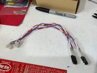
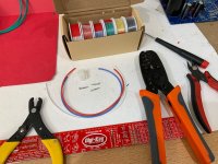
Gather your tools, wire, crimpers, ferrules, and wire stripper:

So the steps are:
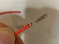
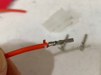
1. strip off 2mm of insulation from the end of the wire (no more as it will interfere with seating action of connector).
2. Place the wire onto the crimp ferrule making sure the insulation is fully under the outermost crimp prongs so that they get a good purchase on the insulation.

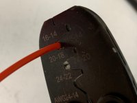
3. Place the conductor part into the smaller of the two crimp jaw dies labeled for the gauge and squeeze crimpers to make a good electrical joint.

4. Pull it out and place the insulator part into the larger die labeled for the gauge, making sure the curved parts of the die is on the side with the prongs, squeeze.
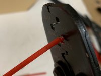
It should look like this after the first squeeze:

Then place into the second (larger) die for the insulation:

On my crimpers, there is a slightly smaller die for the inusulation that I give a third die squueze to really cinch in the clips on the insulator.
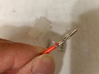
5. You should have a part that has made an excellent crimp metal-to-metal contact for the conductor and a good crimp onto the insulation that provides strain relief and resitance to being pulled apart.
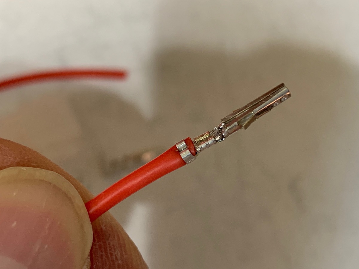
The connections work amazingly well without any solder needed. Resist the urge to solder because it will wick into the flex joints and prevent the connector from working.
You can bang out a bunch of them real quick with all the tools in place:
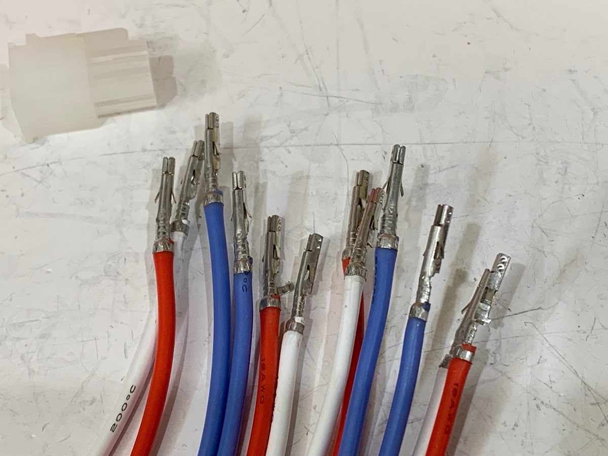
Then insert into the appropriate hole in the shell, taking care to note that there is a propper orintation for the two wing clips (sideways and rounded part on bottom):

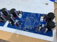
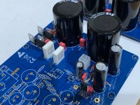
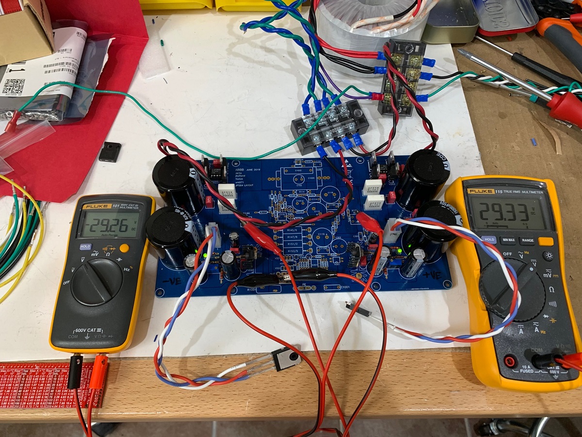
I then tested out the wires connected to the BJTs and the amp board, so far built up with just the SLB PSU portions. All is good, with a test 32v trafo, I get 29vdc after the cap Mx's.
https://www.amazon.com/gp/product/B07476C1LD/ref=ppx_yo_dt_b_asin_title_o00_s00?ie=UTF8&psc=1
Gather your tools, wire, crimpers, ferrules, and wire stripper:
So the steps are:
1. strip off 2mm of insulation from the end of the wire (no more as it will interfere with seating action of connector).
2. Place the wire onto the crimp ferrule making sure the insulation is fully under the outermost crimp prongs so that they get a good purchase on the insulation.
3. Place the conductor part into the smaller of the two crimp jaw dies labeled for the gauge and squeeze crimpers to make a good electrical joint.
4. Pull it out and place the insulator part into the larger die labeled for the gauge, making sure the curved parts of the die is on the side with the prongs, squeeze.
It should look like this after the first squeeze:
Then place into the second (larger) die for the insulation:
On my crimpers, there is a slightly smaller die for the inusulation that I give a third die squueze to really cinch in the clips on the insulator.
5. You should have a part that has made an excellent crimp metal-to-metal contact for the conductor and a good crimp onto the insulation that provides strain relief and resitance to being pulled apart.
The connections work amazingly well without any solder needed. Resist the urge to solder because it will wick into the flex joints and prevent the connector from working.
You can bang out a bunch of them real quick with all the tools in place:
Then insert into the appropriate hole in the shell, taking care to note that there is a propper orintation for the two wing clips (sideways and rounded part on bottom):
I then tested out the wires connected to the BJTs and the amp board, so far built up with just the SLB PSU portions. All is good, with a test 32v trafo, I get 29vdc after the cap Mx's.
Attachments
-
 Crimp-howto-10-test-PSU.jpg465.3 KB · Views: 469
 -
 Crimp-howto-09.jpg354.2 KB · Views: 457
 -
 Crimp-howto-08.jpg278.1 KB · Views: 896
 -
 Crimp-howto-07.jpg173.2 KB · Views: 467
 -
 Crimp-howto-05.jpg252.1 KB · Views: 455
 -
 Crimp-howto-04.jpg198.4 KB · Views: 455
 -
 Crimp-howto-03.jpg196.4 KB · Views: 488
 -
 Crimp-howto-02.jpg151.4 KB · Views: 482
 -
 Crimp-howto-01.jpg387.1 KB · Views: 499
Last edited:
You got the same O-scope as me Vunce!
Ok, I am going to make a double espresso and then start stuffing the core guts of the amp now. The heatsink CPU cooler mounting is what takes time. The PSU with this amp is now done. Usually that’s the most time consuming aspect - connecting the PSU. So convenient to just have to connect a pair of secondaries from trafo and bam! You are done with the PSU.
Ok, I am going to make a double espresso and then start stuffing the core guts of the amp now. The heatsink CPU cooler mounting is what takes time. The PSU with this amp is now done. Usually that’s the most time consuming aspect - connecting the PSU. So convenient to just have to connect a pair of secondaries from trafo and bam! You are done with the PSU.

Thanks X!
I’m running 37vdc after the onboard capMx and .600vdc across the parallel sensor resistors, I believe that’s approximately 2.75A bias current.
All cpu temperatures are very well under control. The Mosfet coolers are running 37°C at the fins and 50°C at the aluminum angle clamp bar.
The amp at idle is silent with my test speaker setup, but I will hold off judgement until I hookup to my main speakers that are very efficient and reveal any noise.
I was listening for about 2hrs tonight using an iPhone—>Bluetooth module with Toslink output into an “old school” R-2R Dac. For only a single channel now, the ABBB sounds wonderful
What’s the secondary rating of your transformer out of interest?
I’m using a 600va, 32v Antek transformer for each channel. You could use a 500va as well.
The 12v tap can be used for a small linear psu to power the fan controller.
AN-6432 - 600VA 32V Transformer - AnTek Products Corp
The 12v tap can be used for a small linear psu to power the fan controller.
AN-6432 - 600VA 32V Transformer - AnTek Products Corp
Last edited:
I’m using a 600va, 32v Antek transformer for each channel. You could use a 500va as well.
The 12v tap can be used for a small linear psu to power the fan controller.
AN-6432 - 600VA 32V Transformer - AnTek Products Corp
Cool - I got 500 VA 32v trannies so should get similar results hopefully
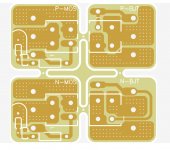
Good news folks. I just got word that the ABBB boards just completed manufacturing and are being packed for delivery to USA. Probably another 5 days before I receive the boards and will send out by next weekend. You will receive at no extra charge, a set of 4 mini boards per amp channel that will let you solder the BJT and MOSFETs to and then the flying leads can be either soldered from there or you can choose to use Molex connectors (premade PC power cables). The mini boards permit installation of a snubber right at the MOSFET pins - Something we found critical to prevent oscillations.
Attachments
Last edited:
Good news folks. I just got word that the ABBB boards just completed manufacturing and are being packed for delivery to USA. Probably another 5 days before I receive the boards and will send out by next weekend....
Excellent news X!
Soon to be newborn ABBB’s out in the wild
- Home
- Group Buys
- The Alpha Big Boy with Buttah (ABBB) 52w Class A Amp GB