
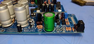
Anyone else noted that the height of the Chem Con 15000uf/63v are 65mm high? I got these yesterday not checking the amp I am assembling and you can't put any standoffs on the PS board so the top of the caps clears to top cover. I think the chassis he sent was the Dispantee 2U chassis with that metal perf board. Since the DC out is only 35 v or so as per Destroyer, anyone else try a bit lower voltage so the height can be reduced? I know we have to keep 35mm wide and pins 10mm apart to fit board. I'll scan Mouser and Digikey to see what else is around.
Anyone else noted that the height of the Chem Con 15000uf/63v are 65mm high? I got these yesterday not checking the amp I am assembling and you can't put any standoffs on the PS board so the top of the caps clears to top cover. I think the chassis he sent was the Dispantee 2U chassis with that metal perf board. Since the DC out is only 35 v or so as per Destroyer, anyone else try a bit lower voltage so the height can be reduced? I know we have to keep 35mm wide and pins 10mm apart to fit board. I'll scan Mouser and Digikey to see what else is around.
On the PSU board 50v caps are just fine. On the amp board do not go below 80v one the ones spec'd for that. Sorry if the general PSU caps I put in are big, part of choosing is related to stock and normally stocked if possible. The width of them is not key, but yes they are "snap in" profile vias.
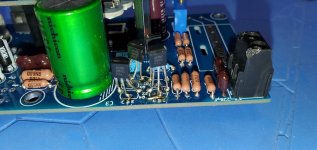
Destroyer, I have a question. I finished one board other than mounting chips, waiting for the insulating wafers. But on the other board 2 of the transistors pads have come off. Q3 base has a trace going to it's collector, I added a small wire to join back traces, also the Q3 emitter to the Q1 collector. These are connected and have added a wire to join them back up.
I am having difficulty tracing where the base of the Q3 comes in or is it just connected to it's collector? I'll ohm out the other board but it has all the resistors mounted. Have you got a partial schematic showing the transistor connections so I can trace out.
Honestly in all my years of doing repairs/kits, I have never seen transistors mounted on pads. Not sure why holes were not designed for this, maybe it's the only way this could have been built. I did see someone else back 3-4 years ago wanted to drill holes..which was not recommended probably due to traces between the boards I assume. If you want I can attach some pix.
I got the traces repaired and ohmed out the paths. Looks ok, will compare to the other board which went ok without any issues. It would have been nice to even have a front end schematic to trace things out but I drew quite a bit of it out. Keep you posted.
That's odd you had pad lifts. It is not a common occurrence. I put solder on a pad, push the leg into it, then do the others as a quick iron touching pad & leg, then solder pushed into the joint.
It's true it is slightly odd having pads but the configuration does have a lot to do with performance. Different layouts measured a good bit different.
You are welcome to email and send pics as well.
It's true it is slightly odd having pads but the configuration does have a lot to do with performance. Different layouts measured a good bit different.
You are welcome to email and send pics as well.
Yes, the first board I did exactly s you mentioned, put a tad of solder on each pad, even added just a bit to the tip of each transistor leg and then solder pushed to the joint. The second board I did it same. Somehow a few pads lifted but the were the Q3 B to C. The Q3 E to Q1 C. Also the Q2 B pad, but I fixed it and I get continuity now to the 1.5M and 18k resistors. Not sure again why these lifted.
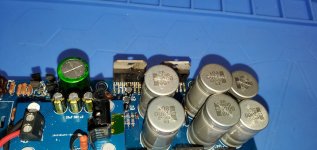
Hey another question, anyone that is using the round transformers , you putting one of the rubber gaskets under the top metal holdown and the other at the bottom of the transformer? I have never used this style of transformers. I would think that would be the best so if it got really hot(which it should not) it would protect the winding from touching some of the top plate or the bottom chassis.
That's what I found online, put one on the bottom, the other under the top holdown plate.
Destroyer, are there any one of the holdown screw holes on the main board that cannot be used with a metal standoff to mount to the bottom chassis?
I have plastic ones and metal ones, I tried a meter and none seem conductive to any one the holes. I did use plastic on 3 of the ones as per your info on the LED board and for the one to be metal to the lower power board . Getting ready to fire this up in a few days and don't want to fry anything. Looking at other pix of finished amps quite a few people are using metal standoffs from the amp board to chassis.
Thanks for all your help.!!
Last edited:
Metal is fine except on the PVI shield hole under the main amp board. The one from main amp board to LED should be metal for the PVI shield, just no support under it unless it is plastic. It does not matter if the none-PVI holes are metal because they are not connected to shield.
I let whomever is building decided how and if they connect to the enclosure, which I would expect to be off of the PSU rather than the amp board.
I let whomever is building decided how and if they connect to the enclosure, which I would expect to be off of the PSU rather than the amp board.
Well good luck on the left channel, amp worked well producing about 63 WRMS at 1khz.
But right channel was ok until I went Just passed 80% on variac, had about 30 volts DC hitting amp board at that spot. Moved variac to full power and poof brew fuse and smoked both power chips. Both were verified as backs not touching ground with wafers behind board.
Bad chips?
But right channel was ok until I went Just passed 80% on variac, had about 30 volts DC hitting amp board at that spot. Moved variac to full power and poof brew fuse and smoked both power chips. Both were verified as backs not touching ground with wafers behind board.
Bad chips?
Attachments
- Home
- Group Buys
- Folsom EC7293: PVI Powered Frontend, 60/120w 8/4ohm