In case anyone else is building this:
I believe pins 2 and 3 on the opamp are swapped around on the pcb layout (not 100% verified yet).
TR3 and 4 need to be fitted in the reverse orientation to the PCB ident.
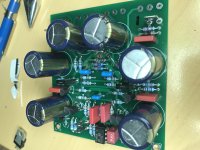
C18 had to fitted under the PCB in my build because there is not enough room for it next to the fast-on terminal.
I would recommend buiding the boards without the output devices for testing. I ran mine off a bench PS which helped me find the reversed TR3,4 without smoke:
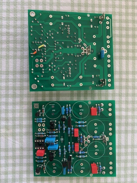
I have left the big caps out for now, to make it easier to jig/align the output FETs.
I had to buy some hex headed screws so that the output devices can be tightened with a spanner, because CP7 & 16 block access to posi or allen headed screws.
I also added some extra mounting holes to avoid stress on the legs of the FETs.
Despite the above caveats it's a nice PCB overall, and I'm looking forward to hearing this amp!
I believe pins 2 and 3 on the opamp are swapped around on the pcb layout (not 100% verified yet).
TR3 and 4 need to be fitted in the reverse orientation to the PCB ident.
C18 had to fitted under the PCB in my build because there is not enough room for it next to the fast-on terminal.
I would recommend buiding the boards without the output devices for testing. I ran mine off a bench PS which helped me find the reversed TR3,4 without smoke:
I have left the big caps out for now, to make it easier to jig/align the output FETs.
I had to buy some hex headed screws so that the output devices can be tightened with a spanner, because CP7 & 16 block access to posi or allen headed screws.
I also added some extra mounting holes to avoid stress on the legs of the FETs.
Despite the above caveats it's a nice PCB overall, and I'm looking forward to hearing this amp!
Thanks for the info Dave, I have 2 of these pcb,s - project for next year now. I was aware of the issue with TR3 and TR4 orientation, but was not aware of the op amp inputs swapped, can you update here when you have verified this for sure, thanks. Have printed out your photo showing the mods on the back of the pcb around the op amp for reference.
C18 is no big deal, and I look forward to your listening impressions when up and running.
Also would be interested in the PSU you have implemented for your build.
Regards,
Gary..
C18 is no big deal, and I look forward to your listening impressions when up and running.
Also would be interested in the PSU you have implemented for your build.
Regards,
Gary..
Stage 2 of testing complete with FETs fitted, then dc servo fitted powered from bench supply:
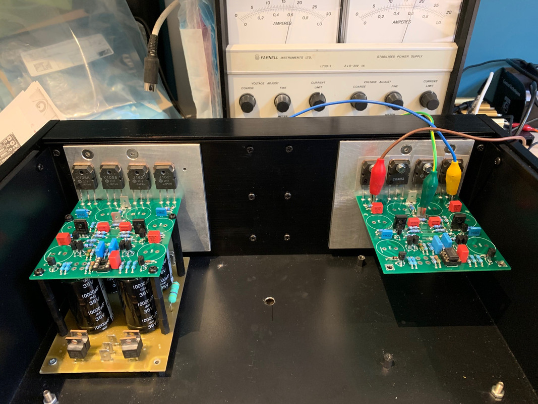
Mine biased up at 560/600mA for the each channel using R17 = 180R.
I can confirm that pins 2 & 3 of the opamp need swapping (need to cut the tracks on the topside).
It's ready for final assembly now.
PS is a pair of toroids and MUR820s + 10KuF-0.47R-10KuF
Mine biased up at 560/600mA for the each channel using R17 = 180R.
I can confirm that pins 2 & 3 of the opamp need swapping (need to cut the tracks on the topside).
It's ready for final assembly now.
PS is a pair of toroids and MUR820s + 10KuF-0.47R-10KuF
Last edited:
The A18 has been running for a day or so. I backed the Iq down to 450mA due to limited heatsink.
I was reading about the Simpelstark amp and came across a quote of a quote, Charles Hansen & Hugh Dean:
https://www.diyaudio.com/forums/solid-state/312866-global-loop-amplification-23.html#post5945700
I think this may well be true!
The sound is just so clear and lacking artifice.
I was reading about the Simpelstark amp and came across a quote of a quote, Charles Hansen & Hugh Dean:
https://www.diyaudio.com/forums/solid-state/312866-global-loop-amplification-23.html#post5945700
I think this may well be true!
The sound is just so clear and lacking artifice.
- Home
- Group Buys
- PCB for the HAWK A18 amplifier (+ FETs if required)