did I do it correctly?
Hi Prasi
I don't want to appear impatient, but I'm not sure if I did everything correctly:
"Subscribed" to the google-doc-sheet with my diva-name, placed my order...
Will I hear from you, or do you need a PM to get my Emailadresse etc.?
sorry for clogging up...
best
david
Hi Prasi
I don't want to appear impatient, but I'm not sure if I did everything correctly:
"Subscribed" to the google-doc-sheet with my diva-name, placed my order...
Will I hear from you, or do you need a PM to get my Emailadresse etc.?
sorry for clogging up...
best
david
Last edited:
Hi David,
No problem, I have your email / address and the requirements @ sr. no.38 of the google list.
As posted above post #841, once the lock-down ends and international shipping starts, I will post here the information and start sending paypal invoices.
regards
prasi
Perfect, thank you!
All the best
David
Thanks, i asked on the Mark Johnson forum and get YES:" I would suspect that it is, since MOSFETS have plenty of Source-Drain capacitance, and its the transformer secondary leakage inductance that Quasi wants to tame."
Looks like a power supply upgrade and on the other side the Prasi pcb as place for it.
It's why i was asking if someone made some test on the sound with and without the 3 components. I'm building a power amp and have 4 Prasi ideal bridges working i want to install in vertical mode with so little space and the secondary solid wires are so thick for the boards .....
Probably i will take your opinion that is , Less is better.
It's a bit hard to be totally sure that the snubber network as per the Quasimodo test will actually be of benefit or not, with different types of transformers, different sizes, for example, etc - but if the parts are handy and the required resistor value known, well, add them onto the board as a 'fail-safe' and know you've 'gone to the max'.
In comparison to the cost of the 'new bridge, the 3 components aren't much extra. I use Wima MKP 150nF and a 10nF Rifa pfe216 styrene (NOS) - the board layout (using the to-220 version) hasn't allowed much room but can fit these underneath, vertically, etc.
I found the LT/fet rectifiers produced a slightly smoother more detailed sound (even with the Cap multiplier rail filters) to the sound of my previous 'best' arrangement using those 'u-beaut' Shindengen Schottky bridges plus the appropriate snubbers.
Maybe the slight extra voltage on the rails produced a slightly more dynamic sound but this is probably my imagination working overtime!
I did add the snubbers (also with good quality caps) to the LT/fet bridge (with the same transformer and supply) but didn't hear any change/difference but it's quite possible that they do make a difference but I just didn't hear it - I didn't use the CRO to check this unfortunately.
Perhaps someone has done this and can add some more information ...
Much thanks for your reply , i asked also to someone who made some experiments with and without the snubber and his opinion is positive .So i will place the components .wima mkp10 600v 150nf ,ero polycarbonate 10nf ,20R 1w phillips carbon, everything monster but the work is done just the solder missing.
Okay, good to know - will go back and try this again and see if I can get a better result - quite possibly, the Cap Mx hides the difference, or I'm just getting 'past it'!
Regardless to the benefits of this great rectifier, the type of the capacitors still dominate the sound of the power supply, not the amount of uFs, and increasing the size sometimes is a backward step in the sound result despite all the rhetoric about low ripple factors, output impedance, etc - this is especially true with these Cap multiplier circuits (and many regulators) and it's good to keep this in mind when choosing the caps, particularly the ones closest to the amp - it's generally only convenience to use the same caps directly behind the diodes (and the LT version too) and on the output but often using different types of caps will benefit desired sound - try it sometime and be surprised!
All the best
All the best
So i will place the components .wima mkp10 600v 150nf ,ero polycarbonate 10nf ,20R 1w phillips carbon
And these random values will fit the DS capacitance like a glove?
")
Dubious, but of course those still have the effect of bypassing the main filter caps and moving resonances which is always audible. Some may like it and others may hate it.
If you have an itch to add random unnecessary components why don't you do it scientifically and check for ringing first? Wasn't the quasimodo circuit developed for just that?
Based on the TH pcb's of Prasi I have successfully build several positive rectifiers with low ripple.
In post 678 the option of dual secondaries was mentioned:
https://www.diyaudio.com/forums/group-buys/336572-lt4320-based-active-rectifier-68.html#post6099881.
Following the instructions, the positive supply shows some 50mV TT ripple. However, the negative supply holds about 4V TT ripple. This was also the case when two separate active rectifiers were used for positive and negative supply (with the positive connected to the negative to set a common ground). As a test, both active rectifiers were wired as only positive supplies, and then a low ripple can be seen again.
Yes, the secundaries are in phase as per instruction.
What do i miss?
Thanks for your reply.
I included the reference to the post 678 to illustrate that exactly that setup is used. If the detailed photo in that post is not enough, of course I can draw the schematic.
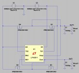
Summary: the setup comprises a transformer with two separate secundaries wired in phase. One end of the wires are connected into a ground. The other ends serve as the AC-input for one single active LT4320 rectifier.
After the rectifier which yields about +/- 20V I have added a simple LM7815-LM7915 in order to get current flowing through the active rectifier. Otherwise it won't start, as mentioned in post 678. After the LM7815-LM7915 the positive voltage is fine, but the negative voltage contains a small hum (probably because of the high negative ripple of 4V).
Before, I have build many dozens of linear regulators. The only difference here is the two secundaries are wired in phase, instead of the classical 'out of phase' for a positive / negative supply.
I wonder what can be tried to further test the setup?
I included the reference to the post 678 to illustrate that exactly that setup is used. If the detailed photo in that post is not enough, of course I can draw the schematic.
Summary: the setup comprises a transformer with two separate secundaries wired in phase. One end of the wires are connected into a ground. The other ends serve as the AC-input for one single active LT4320 rectifier.
After the rectifier which yields about +/- 20V I have added a simple LM7815-LM7915 in order to get current flowing through the active rectifier. Otherwise it won't start, as mentioned in post 678. After the LM7815-LM7915 the positive voltage is fine, but the negative voltage contains a small hum (probably because of the high negative ripple of 4V).
Before, I have build many dozens of linear regulators. The only difference here is the two secundaries are wired in phase, instead of the classical 'out of phase' for a positive / negative supply.
I wonder what can be tried to further test the setup?
Ok. So, it is as expected.
In this particular connection the 4320 works as a half wave rectifier, as i have mentioned many times in these threads. The ripple is obviously much higher.
Using an amp as a load is not a good idea if you want to take measurements. Rather use resistors or active loads, so it is certain that the current draw through both outputs is equal. Under these conditions the ripple on + and - will also be equal.
Hello AV,
whats the transformer voltage of each secondary and what is the output AC of trafo across the wires/ ac terminals.
here is some info.
https://www.electronics-tutorials.ws/transformer/multiple-winding-transformers.html
regards
prasi
whats the transformer voltage of each secondary and what is the output AC of trafo across the wires/ ac terminals.
here is some info.
https://www.electronics-tutorials.ws/transformer/multiple-winding-transformers.html
regards
prasi
This is completely unrelated and can only contribute to further obfuscation. Surprising.
Only having half wave for a dual supply with one active rectifier, I get it now.
The link of Prasi has some use, resulting in a question:
A dual supply can be made by two separate full wave rectifiers with each its own winding. They can can be wired on top of each other by connecting the positive of the lower one to the ground of the top one. This is my favorite setup for a dual supply.
This dual scheme may also be applied on the active rectifier. One active rectifier with its own separate AC winding will yield full wave rectification resulting in a positive voltage. For a dual supply two of such active rectifiers can then be connected on top of each other by connecting the positive of the lower one to the negative of the top one. This will result in a dual supply with full wave rectification. Question: Correct?
@Analog_sa: I will redo the test of post 853 by only adding capacitance and a suitable resistive load. Measurements on ac and dc will follow.
Last edited:
- Home
- Group Buys
- LT4320 based active rectifier