Hello folks,
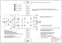
For people looking for a compact solution for crc psu using LT4320, here is a proposal...
The pcb below can be used for dual secondary as well as CT transformers.
1. in case of dual secondary, one could substitute the SIP rectifiers (B1 AND B2) (of the type https://www.vishay.com/docs/84807/pb3506.pdf) with my SMD LT4320 rectifier pcbs. (B3 and its snubbers unpopulated).
2. In case of CT trafo use, you could use the vishay sip rectifier with a heatsink similar to this ATS-PCB1061 Advanced Thermal Solutions Inc. | Fans, Thermal Management | DigiKey . Just cut off the support pins i not necessary.
I am posting a few 3D as well as sch, stuffing guide and gerbers for convenience here again (already posted in apex 100w amp thread but i guess its like finding needle in haystack)
Now the resistors can be 2 of bpr56 /58 -5W each side or 6 of 6mm dia max. axial resistors of 23mm pitch populated from bottom side.
I have tried to explain the use of psu in sch in a detailed manner, do have a careful look. The caps can be 35mm dia max with 10mm pitch-2pin OR 22.5mm pitch-4pin.
regards
prasi
I have read the stuffing guide, studied the schematic and have been reading as much as I can about power supplies to try and not ask too dumb a newbie question.
What are the variables in the schematic that need to be adjusted for different sized/voltage transformers?
Lets assume a 300VA 35v dual secondary transformer.
To me it looks like,
- the obvious, the big main caps (C1..C4) have to be the correct voltage (i.e. 63v caps for 35v transformer)
- snubbers (CX, CS, RS) based quasimodo jig, or left out if using your LT4320 based active rectifier
- LED resistor (R10, R11), based on transformer voltage
My questions are about,
- the filter resistors, R1..R6 or RP1, RP2, it looks like it you use R or RP, but not both, when would you use one vs. the other, and how do you pick the values? R1..R6 are shown to be 1 ohm, is that a fixed value or does it change based on transformer? How many watt should they be and of what type? RP1, RP2 are shown as type BPR 56 5 watt resistors, but what value should they be if used rather than R1..R6?
- the Vishay PB3506, for what sized and voltage transformer are they good til? If and when would you need to go to PB3508 or PB3510?
- R8 and R9 are shown as 1 ohm 1 watt resistors, does the type matter?
- RB and RB' are shown as typical value being 2200 ohms, 3W for 35 volts. Is that typical for a 35v AC transformer or a rectified DC voltage of 35v?
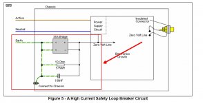
- For the ground pad between the bulk caps, I looked around the Elliot Sound Products web site and didn't find the information about for connecting it to the chassis via a disconnect network, I thought this search would have worked "disconnect network" site:Elliott Sound Products - The Audio Pages (Main Index) . Does anyone have any direct links where I can read specifically about his?
Sorry for such basic questions.
David.
Last edited:
My questions are about,
- R8 and R9 are shown as 1 ohm 1 watt resistors, does the type matter?
Sorry, I don’t have many answers (I received my PCBs today and is just now reading through the thread to figure out how to build it), but I noticed that the schematic appears to show R8,9 to be 1 Ohm 0.25 Watt resistors. I believe either metal or carbon film resistor would work well.
- Home
- Group Buys
- LT4320 based active rectifier
 .
. 
