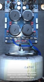
Thanks Anand! I knew I had seen it somewhere, but just didn't find it!@Nikodemuzz
Go back to the beginning of this thread, specifically post #35, all is explained there.
Best,
Anand.
I'm finally getting close to ordering my transformers, and thinking about going with Toroidy instead of Antek.
All of Toroidy's standard transformers are listed as 230V input. But I'm in the US, so I have 120v / 60Hz power. So if I did the math correctly, I believe a transformer rated for (230v input / 42v output) should give 22V output when connected to 120V input.
First, is my math/thinking correct here?
Second, can this actually be done, or are there other factors at play I'm not thinking of that make this a bad idea?
I'm trying to avoid the additional cost of a custom transformer. I have my eye on their (non-supreme) audio grade, which before shipping and when accounting for the ability to use a 50 or 100VA smaller size due to the reduced sag under load vs Antek, do not seem much more expensive than Antek. We'll see if shipping to the US changes that though.
I doubt it makes a difference, but I'm planning a Dual-mono PS for PassDIY/FW designs. Aleph J and M2x first. Thinking about a 200 or 250VA Toroidy per channel.
Last edited:
If your going to order from Toroidy you might as well go custom to get exactly what you want. You can use a single 400-500va trafo, 120v primary and 4 secondaries. That will save some chassis space and get you a dual mono psu. Be prepared for shipping cost and a bit of a wait...... Awesome transformers though, definitely worth it IMO. 

Hmm alrighty, I’ll request a quote. I was under the impression that it was best to have separate toroids for each channel in a dual mono setup so a deep bass hit on one channel doesn’t suck current from the other channel. Maybe that’s not enough of a thing to matter though if your single (4 secondary) transformer is 2x bigger rated capacity than the single (2 secondary) transformer NP uses in the commercial FW amps? Am I correct in remembering that he uses a single 300VA in the commercial FW amps?
Quite right, PFE, but if you are using a powerful regulator there is no point in having two separate trafos.
The SLB will deliver two independent power supplies anyways, so an expensive Toroidy might just be a single monster.......
Thanks Vunce!
HD
@pinkfloyd4ever
In example…but a bit extreme...this is the toroid/supply configuration used with my current Alpha Nirvana build. With 20V secondaries, I am getting ~ +/- 23-24V under load (1.3A-1.5A). The 800VA Toroidy in particular has very good internal regulation and little voltage lag with these ”small” Class A builds (I chose it since the NPXP is really a test mule). Keep in mind that my line voltage isn’t always 120VAC. Sometimes 119VAC and other times 122VAC. You have to factor that into your builds as well.
If I were building just a single design, I would probably stick with 600VA w/quad secondaries. But that’s me, I live on the lunatic fringe and you live only once. Reliability, low noise and low heat mean everything to me.
I have been brainstorming an Aleph 60 stereo build (4U/500) whose design center is around +/- 34V to +/- 35V at 2.2A. I might go with a 1KVA Toroidy, quad secondaries @28VAC for that one.
Best,
Anand.
Last edited:
Interesting. But then I just saw this discussion between Russellc and ZM https://www.diyaudio.com/community/threads/aleph-j-illustrated-build-guide.241729/page-422 which makes me question it all. Thoughts?
I am often the king of overthinking things and thus, indecisiveness.
Oh yes, Anand, I've been following your NPXP closely. I have been envisioning doing something similar for awhile, and your NPXP has been a great inspiration and confidence booster that what I've had in mind will in fact work.
The one (more practical) consideration that makes me think the potted "Supreme audio" version might be worth the extra cost (besides the fact that it looks awesome) is the fact that I'd like to put an M2x in this beast at some point, and I've read there can sometimes be noise issues with the M2x autoformer picking up stray EM noise from the power transformers.
I'm afraid I'm going to have to ask for some guidance.
I populated first of my two double-rail SLB's yesterday, and proceeded to test it today, with not so great results.
For background, I will be using a soft start board in my amp, and have already completed that. In my testing with a light bulb it seems to work as intended. The board in question is the EU version of this design presented in post #545: https://www.diyaudio.com/community/...soft-start-h9kpxg.354971/page-28#post-6996675
I'm using a Triad 2X24V 250VA transformer. I measured that it is outputting the correct voltage before connecting the SLB.
Now, when I connect SLB and power up, the fuse (5A slow blow) on the soft start board blows within a few seconds. Output voltage from the SLB rises to about 15V but doesn't have the time to stabilize.
There was no smoke, no smell, and visually I don't see anything wrong. The soft start still works when I use it with the light bulb. The build itself I felt was quite straightforward, the one thing that left me with an uneasy feeling was the orientation of Q9 and Q11. On the BD139 was clearer, with the metal plate to go against the heat sink, but on the BD14016 I didn't see an obvious way to tell which is pin 1, even from the datasheet. I installed it "visually" the same way as the BD139.
I'm attaching a few photos, perhaps you can immediately see something amiss?
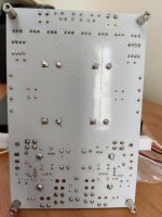
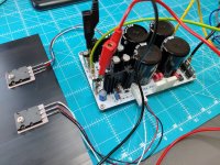
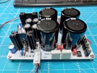
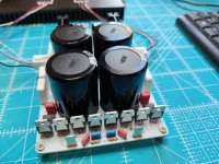
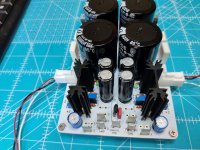
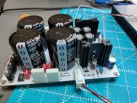


Thanks for the quick help @Vunce!Hi Niko,
Looks like your SLB AC input is incorrectly connected. The SLB requires a transformer with 2 secondary windings.
Secondary#1 connects to AC1 (J1/J2) and secondary#2 connects to AC2 (J3/J4).
Somehow I completely overlooked that. I saw it in the schematics, and for some reason thought it was optional... Luckily that is easy to fix. I'll make the correction and report back.
Hi Nikodemuzz,
Sorry to hear you had troubles on startup, and I hope that did not fry components on your SLB board. The SLB dual rail requires two separate secondaries and cannot be used with a center tapped transformer as the LT3420 is not compatible with center tapped topology.
Thanks to Vunce for replying.
Sorry to hear you had troubles on startup, and I hope that did not fry components on your SLB board. The SLB dual rail requires two separate secondaries and cannot be used with a center tapped transformer as the LT3420 is not compatible with center tapped topology.
Thanks to Vunce for replying.
Thanks @xrk971! I'm hoping everything is still OK as well. The transformer I have is a dual secondary one. I just happened to have a brain fart and connected the secondaries in series like I had done in some earlier projects...Hi Nikodemuzz,
Sorry to hear you had troubles on startup, and I hope that did not fry components on your SLB board. The SLB dual rail requires two separate secondaries and cannot be used with a center tapped transformer as the LT3420 is not compatible with center tapped topology.
Thanks to Vunce for replying.
OK, I fixed the transformer connection. No more fuses blowing, but things aren't quite right yet either...
First of all, I think I indeed have wrong transformers. These are 24V with secondaries in series, 12V in parallel. Since I had failed to understand the way the transformers are meant to be connected (although it is mentioned here several times, I believe...) I think I have now transformers that produce half the voltage they should.
Secondly, I measure 16,7V on NVout, and 0,2V on PVout (between ground and the respective terminal). I'll need to go round the board and take a bunch of measurements to see what is going on.
Hi @AKSA! You mean something like this?Yes, NKD, you may need to buy new transformers.
Can you send us a wiring picture of your transformer to confirm?
HD
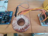
I'm pretty sure I got the wrong kind. It's 2X12V.
Thanks for the photo - helpful, but I have the impression this has two independent secondaries, perhaps each 12Vac?
If so, as you mentioned, not enough volts. You need about 25Vac from each winding if you are using the SLB since it will drop about four volts.
Do you have a schematic and color code from the transformer manufacturer?
HD
If so, as you mentioned, not enough volts. You need about 25Vac from each winding if you are using the SLB since it will drop about four volts.
Do you have a schematic and color code from the transformer manufacturer?
HD
I was just dry fitting my Q9 & Q11 transistor/heatsink assemblies, and noticed that when they're soldered in place, the adjustment screw on RV2 will be inaccessible because the mounting screw for Q11 is directly above it. How do you adjust RV2 once these are soldered?

Has anyone else run into this problem or did I do something wrong?
Has anyone else run into this problem or did I do something wrong?
Last edited:
You didn’t do anything wrong. It’s a small oversight from the original board design. I have been recommending folks (like Sledwards did in his Alpha Nirvana build you have seen on the AN thread) that they flip RV2 around so that the screw is accessible. It won’t affect anything. You’ll just twist the screw the other way while you are setting your output voltage.I was just dry fitting my Q9 & Q11 transistor/heatsink assemblies, and noticed that when they're soldered in place, the adjustment screw on RV2 will be inaccessible because the mounting screw for Q11 is directly above it. How do you adjust RV2 once these are soldered?
Has anyone else run into this problem or did I do something wrong?
Good on you for picking up on this in advance of soldering.
And just so you know, both RV1 and RV2 only adjust the output voltages by about +/- 1.5V tops. The best way to adjust them, is to hook up your scope on the output of the power supplies and adjust the voltage for lowest voltage ripple (which is already uber low anyway…like <2 mV). Don’t worry about this too much if you don’t have a scope. Just set and it and forget it (famous rotisserie infomercial!).
Best,
Anand.
Last edited:
- Home
- Group Buys
- The SLB (Smooth Like Butter) Active Rect/CRC/Cap Mx Class A Power Supply GB
