It's Like Buttah!!!
After some discussions we decided to remove the 10R resistor at R17 and R18 to buy back some gain that should squash the ripple even more. R17 and R18 are there to prevent oscillations should they occur, but do so at the detriment of ultimate ripple eating performance. So I removed the 10ohm resistors and replaced with a jumper. You could keep a 2R2 or even 1R5 there if you are chicken. But if you fry a $2 Toshiba 2SA1943N or 2SC5300N, no big deal. I monitored the output voltage with an o-scope during the power up and saw a small 50mV MHz range oscillation that was in a burst mode, but as soon as the voltage stabilized (5-10 seconds) the oscillation went away. What we are left with is pure magic. Here is 35.4v output into an 8ohm load for 4.43A current with a 3.1v drop across the CFP slave 2SA1943N transistor, and even at high current, the ripple is about 1mV. I measured 1.2mVrms on the postive rail and 0.9mVrms on the negative rail for the same condition. The negative rail had no startup oscillation.
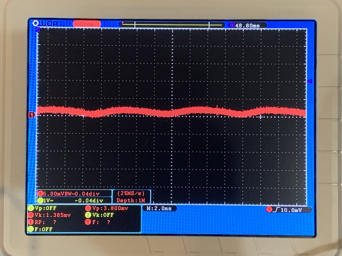
This O-scope shot is on the 5mV per division vertical scale, and you can see the output. It's a tall order to ask a PSU with only 30,000uF bilk capacitance to give 1mVrms ripple under a 4.4A load. This means that one of these PSU's will have plenty of ripple eating ability for powering a stereo amp. The only thing one needs to be careful with are ground loops when sharing a PSU between two channels.
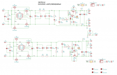
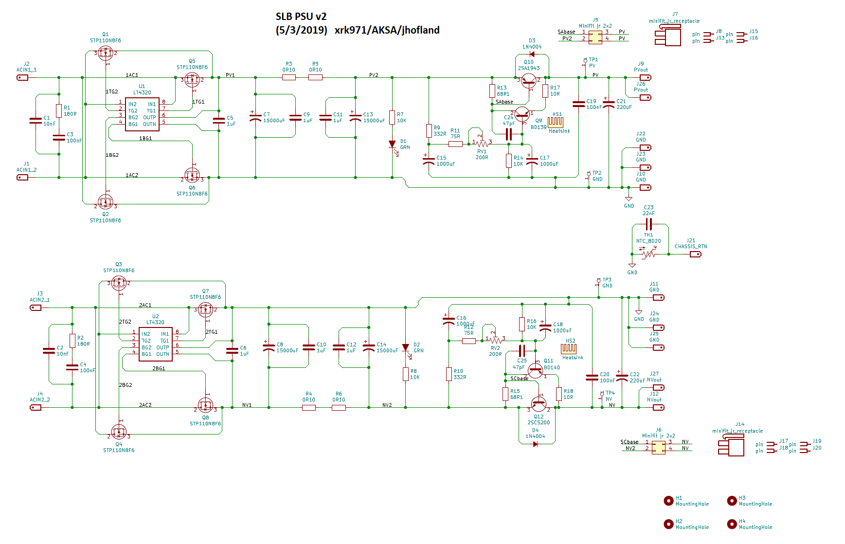
Here is the schematic of the production board (v2, May 3) with extra sets of output spade terminals for use as a stereo PSU:

In the above schematic, replace R17/18 with either jumper if you are brave or a 2R2 if not. Although a !R would probably squelch the startup oscillation nicely and give about same performance.
After some discussions we decided to remove the 10R resistor at R17 and R18 to buy back some gain that should squash the ripple even more. R17 and R18 are there to prevent oscillations should they occur, but do so at the detriment of ultimate ripple eating performance. So I removed the 10ohm resistors and replaced with a jumper. You could keep a 2R2 or even 1R5 there if you are chicken. But if you fry a $2 Toshiba 2SA1943N or 2SC5300N, no big deal. I monitored the output voltage with an o-scope during the power up and saw a small 50mV MHz range oscillation that was in a burst mode, but as soon as the voltage stabilized (5-10 seconds) the oscillation went away. What we are left with is pure magic. Here is 35.4v output into an 8ohm load for 4.43A current with a 3.1v drop across the CFP slave 2SA1943N transistor, and even at high current, the ripple is about 1mV. I measured 1.2mVrms on the postive rail and 0.9mVrms on the negative rail for the same condition. The negative rail had no startup oscillation.
This O-scope shot is on the 5mV per division vertical scale, and you can see the output. It's a tall order to ask a PSU with only 30,000uF bilk capacitance to give 1mVrms ripple under a 4.4A load. This means that one of these PSU's will have plenty of ripple eating ability for powering a stereo amp. The only thing one needs to be careful with are ground loops when sharing a PSU between two channels.
Here is the schematic of the production board (v2, May 3) with extra sets of output spade terminals for use as a stereo PSU:
In the above schematic, replace R17/18 with either jumper if you are brave or a 2R2 if not. Although a !R would probably squelch the startup oscillation nicely and give about same performance.
Attachments
Last edited:
Brilliant, X. It seems that with ripple at 1mVrms even a low PSRR Class A would sound utterly quiet. It occurs to me that using a single darlington like a BD679/680 in place of the BD139/140 we would be able to get the ripple down another ten times for a stellar result. But we chose BD139/140 for good dissipation, low cost and slow speed as we knew the CFP configuration is famous for instability.
Do you have any emitter resistors, ballast, on the slave transistor? We only use one device here (Pd is around 13.5W, only one device needed) and if it is stable, arguably ballast resistors need not be either reduced or even used.
Thank for letting us know what and exactly and how you gone about it. This is a primer for anyone studying linear power supply design.
Hugh
Hi Hugh,
There is no ballast resistor on the 2SA1943N slave BJT. It is exactly as it appears in this schematics (except jumpers provided at R17/18):
And even at 7mVrms, a low PSRR SE Class A amp does sound so quiet I cannot tell is is even on by listening to speakers when source is not playing music. 1mV must sound even more quiet.
Last edited:
Hi X. Reference your post over on the MoFo thread;
https://www.diyaudio.com/forums/pass-labs/313649-build-mofo-205.html#post5781065
will this group buy cover provsion of the single rail version?
If so I'll take a couple (ad be happy to combine shipping with the dual rail boards I've already ordered even if it means waiting).
Cheers
https://www.diyaudio.com/forums/pass-labs/313649-build-mofo-205.html#post5781065
will this group buy cover provsion of the single rail version?
If so I'll take a couple (ad be happy to combine shipping with the dual rail boards I've already ordered even if it means waiting).
Cheers
Hi NB,
Sure, we can start thinking about the single rail version of the SLB now that we know the layout is good. It’s basically the top half of the SLB board. We will have to wait for Jhofland to make the layout.
Let’s call it the SLB-SR, and simply specify SLB or SLB-SR in the GB list. Pricing will be $17ea for the SLB-SR. Note that cost of boards is mostly based on the single maximum dimension, and not the surface area.
If you are using a Class AB amp that may require a current draw beyond the output impedance of the cap multiplier (and beyond 5A continuous draw) that may not be desirable. The output impedance of the CFP slave transistor - in this case, is quite low and equal to the output stage of most amps using a similar BJT. For most Class AB amps in the 50w to 100w range, I don’t believe that the SLB is going to be a limiting bottle neck for the music program. Hugh may have more comments regarding use of SLB for other amps. Most well designed Class AB amps will have higher PSRR so may not benefit as much from having an ultra quiet PSU like a SE Class A amp would.
Last edited:

Hi NB,
Sure, we can start thinking about the single rail version of the SLB now that we know the layout is good. It’s basically the top half of the SLB board. We will have to wait for Jhofland to make the layout.
Let’s call it the SLB-SR, and simply specify SLB or SLB-SR in the GB list. Pricing will be $17ea for the SLB-SR. Note that cost of boards is mostly based on the single maximum dimension, and not the surface area.
Thanks x. I did thnk about buying a couple more dual rail boards and simply removing the negative half but a single rail board will be a much more elegant solution.
Count me in for two SLB-SR boards and invoice when you're ready to go. Happy to wait for delivery so all four boards ship together - I assume it'll save on shipping costs.
Hi x -
The original list appears to be out of date now, but could you count me in?
I've gotten a little confused (probably just my age) but I have both two 200VA 22v transformers and one 300VA 22v transformer, and want to build one of those "typical class A" amps calling for 24v rails in a store 4U Deluxe chassis. Suggestions from the crowd on how to proceed, and therefore how many boards? TIA - Pat
Last edited:
I was thinking about just using the single rail on the dual board as well, but using just the rectifier portion of the other rail to create a separate positive rail (not using the cap multiplier on that rail.) It would be for the DC filament heater of the preamp tube, which has its own CCS for ripple.
See any issues as to pulling the output off that 2nd rectifier for other uses like this?
See any issues as to pulling the output off that 2nd rectifier for other uses like this?
After some discussions we decided to remove the 10R resistor at R17 and R18 to buy back some gain that should squash the ripple even more.
I think you'll have a few Eureka moments if you select the emitter degeneration resistor values in a Complementary Feedback Pair, to be integer multiples of the effective emitter resistance (1/gm).
Step RdegenNPN = (1/gmNPN), (2/gmNPN), (3/gmNPN), ... etc
and also
Step RdegenPNP = (1/gmPNP), (2/gmPNP), (3/gmPNP), ... etc
Since gm is inversely proportional to absolute temperature, you'll want to calculate gm at the forecasted operating temperature.
Plot "gain" (the quantity you wish to "buy back", through changing resistors) versus these integers. Eureka! There exists a wide spectrum of design choices. Many many possibilities besides Max and TooLittle.
I was thinking about just using the single rail on the dual board as well, but using just the rectifier portion of the other rail to create a separate positive rail (not using the cap multiplier on that rail.) It would be for the DC filament heater of the preamp tube, which has its own CCS for ripple.
See any issues as to pulling the output off that 2nd rectifier for other uses like this?
That would work fine and you could use smaller bulk caps and perhaps a linear regulator like 78xx.
I was thinking about just using the single rail on the dual board as well, but using just the rectifier portion of the other rail to create a separate positive rail (not using the cap multiplier on that rail.) It would be for the DC filament heater of the preamp tube, which has its own CCS for ripple.
See any issues as to pulling the output off that 2nd rectifier for other uses like this?
Yes, I had similar thoughts but the second rail I would need (for a gyrator loaded 4P1L driver stage for my MoFo project) needs to be up towards +200V, however, I'm not sure the active rectifier on the negative section could be used anyway as it I believe the pinout of the mosfets means it isn't as simple as reversing them on the board? My observation is based on the picture of the PCB in the first post which shows the board has a connection between the grounds lines of the two sections.
Last edited:
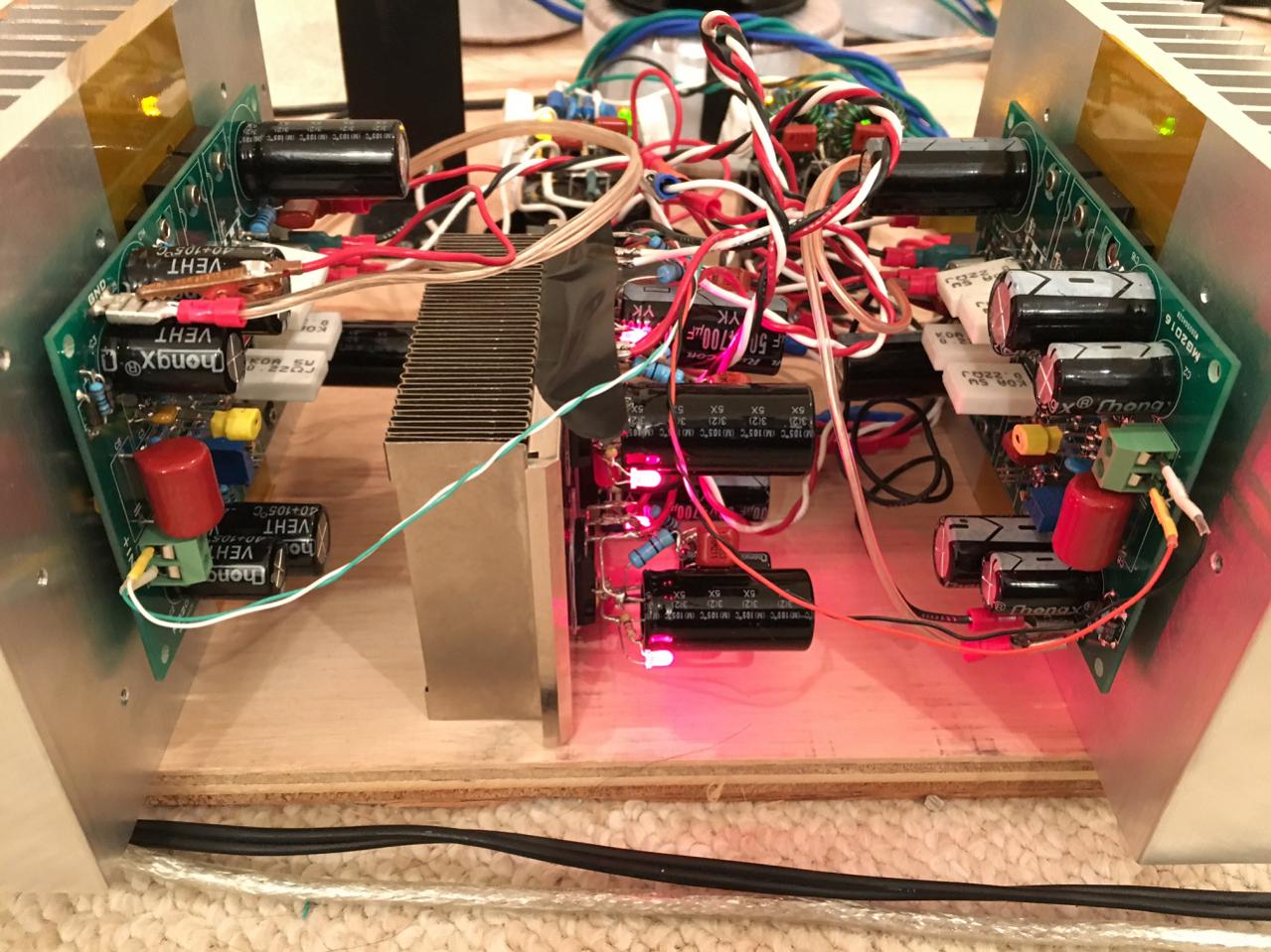
I have used a cap Mx before on a Class AB, and personally really liked the sound - much deeper blacks in the background. I added a 22,000uF cap array consisting of 22 x 1000uF caps in parallel to give a very low ESR charge reservoir after the cap Mx and that increases the bass authority on very deep excursions. I found no detriment - it made the amp sound much better. I talk about it on the CFH7 thread. The only downside is the circa 3v drop so you need to size your trafo voltage one notch higher.
CFH7 Amp
You can see that cap Mx in the middle
CFH7 Amp
You can see that cap Mx in the middle
Last edited:
Hi x -
The original list appears to be out of date now, but could you count me in?
I've gotten a little confused (probably just my age) but I have both two 200VA 22v transformers and one 300VA 22v transformer, and want to build one of those "typical class A" amps calling for 24v rails in a store 4U Deluxe chassis. Suggestions from the crowd on how to proceed, and therefore how many boards? TIA - Pat
You have lots of choices. Two SLBs and two 200VA 22v trafos for dual monoblocks is good. Or one SLB and one 300VA 22v trafo works too. I would do the dual mono lock personally. The stereo separation and imaging is better. Plus the ground loops possibility is reduced. I will add you to list when I get a chance.
Both will get you circa 24v after the SLB.
- Home
- Group Buys
- The SLB (Smooth Like Butter) Active Rect/CRC/Cap Mx Class A Power Supply GB