On the amp I'm assembling with the SLB, I loaded the power supply to 2.1Adc which in turn draws 1.45Aac from the mains line. This simulates (and matches) the mains current draw from a working M2. At this load I have 27.5Vdc coming from the SLB. All this to determine whether the M2X can withstand the output voltage coming from the SLB (27.5V).


Hello X;
I do not solder input filter (R1, C1, C3) and ideal bridge rectifier.
Instead, I run SLB with 4 pcs 6A, 400 PIV, rectifier diode. I do not see any change on ripple on 24v 3 A load with 6 digit multimeter. I guess rest of the circuit did well and eliminate the noise from diodes.
Due to i do not have osiloscope i do not have a chance to test it like you do. I am glad if you can you validate me in your free time.
Thanks in advance...
Last edited:
On the amp I'm assembling with the SLB, I loaded the power supply to 2.1Adc which in turn draws 1.45Aac from the mains line. This simulates (and matches) the mains current draw from a working M2. At this load I have 27.5Vdc coming from the SLB. All this to determine whether the M2X can withstand the output voltage coming from the SLB (27.5V).
View attachment 844986 View attachment 844987
I think you may find the drop is a bit more than that...
Hello X;
I do not solder input filter (R1, C1, C3) and ideal bridge rectifier.
Instead, I run SLB with 4 pcs 6A, 400 PIV, rectifier diode. I do not see any change on ripple on 24v 3 A load with 6 digit multimeter. I guess rest of the circuit did well and eliminate the noise from diodes.
Due to i do not have osiloscope i do not have a chance to test it like you do. I am glad if you can you validate me in your free time.
Thanks in advance...
I used to use diode bridges and noticed a quieter background with the LT4320. Its subtle - but audible if your amp is extremely quiet. The measurement of the output on an OScope will show significantly quieter signal with SLB and LT4320. Depending on bandwidth of multimeter - you may not catch the high frequency ringing from a trafo and diode - which is why people have snubbers. But a snubber isn’t really needed here.
On the amp I'm assembling with the SLB, I loaded the power supply to 2.1Adc which in turn draws 1.45Aac from the mains line. This simulates (and matches) the mains current draw from a working M2. At this load I have 27.5Vdc coming from the SLB. All this to determine whether the M2X can withstand the output voltage coming from the SLB (27.5V).
View attachment 844986 View attachment 844987
I’m pretty sure most Class A amps designed for +/-24v can run fine at 27.5v as long as the heatsinks can handle the extra dissipation. You get a few extra bonus watts in power. Make sure your rail caps are rated higher than 25v though.
I think you may find the drop is a bit more than that...
With the M2X boards connected the voltage drops to 27Vdc and it draws 1.85A from the wall. The amp seems quite happy at this voltage with heat sinks running around 50°C. All capacitors are rated well above 27V. The amp sounds wonderful, is much quieter, and seems to have deeper bass then with the previous PS.
With the M2X boards connected the voltage drops to 27Vdc and it draws 1.85A from the wall. The amp seems quite happy at this voltage with heat sinks running around 50°C. All capacitors are rated well above 27V. The amp sounds wonderful, is much quieter, and seems to have deeper bass then with the previous PS.
Yup, that's about what I see too, about .5V less than what you figured. Temps right on par with mine too.
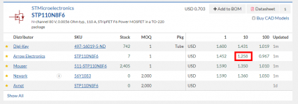
If you get rid of the pricey controller ICs and the numerous MOSFETs, you can save ( (2 x $9.09) + (8 x $1.26) ) = $28.26 .
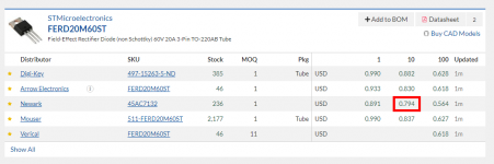
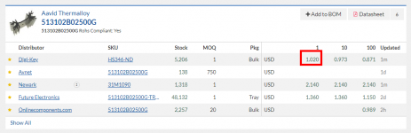
If you replace them with low-but-not-zero-forward-voltage-drop diodes like the FERD 20 ampere parts, you save money but lose 2 x Vfwd volts of headroom. I think there's a very good chance that the FERDs in TO-220 packages would run cool enough without heatsinks, to remain within their datasheet Absolute Maximum junction temperature rating. But to be extra extra cautious, you could mount two diodes per heatsink, using one of the excellent extruded aluminum heatsinks by Aavid.
The diodes cost (8 x $0.80) and the heatsinks cost (4 x $1.02) which totals $10.48 .
So your net dollar savings would be $17.78 ... but you lose 2 x Vfwd volts of headroom. I've attached the diode datasheet so you can calculate the exact number of millivolts Vfwd represents, in your personal situation "on Class D/H amplifier".
_
Attachments
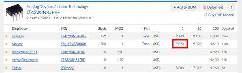
We had considered making the active bridge using MSOP12 IC’s $6ea and SMT low RDSon Dual-MOSFETs $2ea. That would have $20 total cost and fewer and much smaller parts to solder. But only saves $8 overall - so thought the more expensive but more accessible due to TH soldering to be the right choice.
In the scheme of things DIY (not production manufacturing) $10 or $17 savings isn’t worth it IMO.
If using for high transient or pulsed operation maybe add a bank of low ESR bulk caps after the SLB and as close to your amp as possible with thick low impedance wires.
In the scheme of things DIY (not production manufacturing) $10 or $17 savings isn’t worth it IMO.
If using for high transient or pulsed operation maybe add a bank of low ESR bulk caps after the SLB and as close to your amp as possible with thick low impedance wires.
I do not fully understand. the suggested samitec is 2.2 euro but EPCOS is 0.5 euro;
B57153S0100M000 EPCOS / TDK | Mouser Europe
Am i missing something here?
B57153S0100M000 EPCOS / TDK | Mouser Europe
Am i missing something here?
Thanks Mark and X;
for the mains soft start 8d-20 is fine but for ground loop breaker 8D2-07LD suggested in the BOM. Itt is rated 2amp. So the current is not important for the ground breaker right?. 8-10ohm and few mA is enough.
You can use the 8D-20 on the GLB also.
I am working on my 'butta board' and I was wondering if MJ's point about the C24-C17 being in series and potentially problematic has been addressed/resolved. It was a few too many posts ago to search.
By the way, I would reposition J1 and J4 to be side by side with J2 and J3, the way they are now seems way too close to the back of the mosfet. I am going to have to buy insulated female fast-ons...
By the way, I would reposition J1 and J4 to be side by side with J2 and J3, the way they are now seems way too close to the back of the mosfet. I am going to have to buy insulated female fast-ons...
I am working on my 'butta board' and I was wondering if MJ's point about the C24-C17 being in series and potentially problematic has been addressed/resolved. It was a few too many posts ago to search.
By the way, I would reposition J1 and J4 to be side by side with J2 and J3, the way they are now seems way too close to the back of the mosfet. I am going to have to buy insulated female fast-ons...
C24 (optional) was there in case we experienced instability. We can think about repositioning the input AC fastons on the next gen board. I have not had any issues as I always use insulated Fastons.
By the way, I would reposition J1 and J4 to be side by side with J2 and J3, the way they are now seems way too close to the back of the mosfet. I am going to have to buy insulated female fast-ons...
We can think about repositioning the input AC fastons on the next gen board. I have not had any issues as I always use insulated Fastons.
IMO, the current positioning of J1-J4 is fine - and I have used uninsulated spade connectors. Simply bend the diodes back against the caps, slightly - to give you more space.
However, what does annoy me is the lack of space between spade connectors at the output end of the board. In addition, if you are going to continue to recommend an 8D-20 for the SLB ... please adjust component positioning to allow for its large size. (I have mine sticking up from the board - ie. with long leads - which looks ugly.)
Andy
@andyr
Yes you point of all the output fastons next to each other is very well taken!
Of course you can bend-push and shove but it's just not the way to design a board. Also the overuse of ground planes is extremely painful to deal with. The soldering loops around caps and resistors couldn't be made any smaller either!
I had to whip out my 80W big daddy soldering iron to flow the 4 filter caps. Overall I am much less impressed with the board now after spending the day working with it. It seems to be designed for machine stuffing and soldering.
The M2x on the other hand is a real pleasure to work with.
Last edited:
- Home
- Group Buys
- The SLB (Smooth Like Butter) Active Rect/CRC/Cap Mx Class A Power Supply GB