Q9 & Q11 will be fine with small finned extruded aluminum HS.
The BJT’s (Q10 & Q12) definitely need to be mated to heatsinks capable of dissipating the heat they generate from the voltage drop across them.
Thanks, Vunce - that's TTA1943(Q) and TTC5200(Q) in the Mouser shopping cart, right?
Can you tell me how I calculate the heat load?
My own attempt at this calculation (for 1x SLB per channel) is:
* 18v secondaries on the power traffos.
* so 25v after the rectifiers.
* output from SLB +/-20v.
* so 5v drop.
* 3a current (for the 4N version).
* so 15w.
Q1: am I correct in the above calc?
Q2: I have some heatsinks which are rated '9.9KW'. Are these OK?
(As you might guess ... I don't understand what '9.9KW' signifies!
 )
)Thanks,
Andy
The typical voltage drop across the BJT on the SLB is from 2v to 3v, never 5v. Simply your amp’s bias current x drop. Worst case is 3v x 3A is 9w per BJT or 18w per channel.
Thanks, X.
So 9w per BJT - is a heatsink which is rated '9.9KW' OK?
Andy
I don’t know what a 9kw heatsink is? 9 kilowatts? That would be huge.
Usually they are rated deg C/W. In my experience, approximately 4sq inches x 1in deep fin radiator is plenty for 10w. If you get a small GPU or LED lighting cooler with a little fan, that will work.
These may work:
AliExpress
Usually they are rated deg C/W. In my experience, approximately 4sq inches x 1in deep fin radiator is plenty for 10w. If you get a small GPU or LED lighting cooler with a little fan, that will work.
These may work:
AliExpress
I don’t know what a 9kw heatsink is? 9 kilowatts? That would be huge.
Usually they are rated deg C/W. In my experience, approximately 4sq inches x 1in deep fin radiator is plenty for 10w. If you get a small GPU or LED lighting cooler with a little fan, that will work.
These may work:
AliExpress
My mistake, X.
It is specced at 9K/W ... which is the same as 9C/W.
Is that suitable for a 9w heat load?
Andy
Here’s how you calculate it. Multiply watts dissipated by that number and you get a temp rise in C. Add that to ambient and see if it’s 55C or below. 81+22C is 103C and will burn your hands and melt anything that touches it. Also means that the BJT is maybe 120C and that’s not good for it. So you are aiming for no more than about 35C rise. 35/9 is about 3.5C/W rating is what you are looking for from a heatsink.
Here’s how you calculate it. Multiply watts dissipated by that number and you get a temp rise in C. Add that to ambient and see if it’s 55C or below. 81+22C is 103C and will burn your hands and melt anything that touches it. Also means that the BJT is maybe 120C and that’s not good for it. So you are aiming for no more than about 35C rise. 35/9 is about 3.5C/W rating is what you are looking for from a heatsink.
Aah, thanks for the explanation, X.
Andy
Hi andy, on this scorching hot day
I had a brief look at our local electronic suppliers and there's a couple of possible options - there's not much available on the shelves but if you lookup the Altronics H0580 heatsink, it's 75mm high (along the fins) so you could cut this in half (simple hacksaw & vice) to get about 2.8*C/W and be about 36mm high and has the flat back for mounting and the fins offer easy screw mounting on the case bottom plate, for example) - costs about A$13 so not expensive - their H0560 @ 2.2*C/w ( and H0563 @1,3*C/w with 100mm length = 2 x 50mm pieces) will do too - Jaycar have the similar items.
Other suppliers probably have more (Mouser do, for example) have more 4xatly 3.5*C/w units but there's nothing much at Rockby.
Hi andy, on this scorching hot day
I had a brief look at our local electronic suppliers and there's a couple of possible options - there's not much available on the shelves but if you lookup the Altronics H0580 heatsink, it's 75mm high (along the fins) so you could cut this in half (simple hacksaw & vice) to get about 2.8*C/W and be about 36mm high and has the flat back for mounting and the fins offer easy screw mounting on the case bottom plate, for example) - costs about A$13 so not expensive - their H0560 @ 2.2*C/w ( and H0563 @1,3*C/w with 100mm length = 2 x 50mm pieces) will do too - Jaycar have the similar items.
Other suppliers probably have more (Mouser do, for example) have more 4xatly 3.5*C/w units but there's nothing much at Rockby.
Thanks, James.
I had searched on Altronics' web-site and found their H0522. The latter says it's 2.2C/W - so that would seem to be a good one!
I'm tight for space - so 4x H0580s wouldn't be able fit! But 4x H0522 will - although I'll have to use small right-angle brackets to be able to mount them vertically (ie. with the 105mm length going upwards).
There's also DigiKey's FA-220-64E-ND (3.0 C/W). 4 of these would fit better in my case - but there's a delivery charge involved ... whereas I can just pick up the Altronics ones!
Andy
Hi Andy,
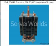
If your CPU coolers have large enough pads, install a MOSFET from the amp board and a BJT from the power supply on each CPU cooler. Those coolers should have no problem taking care of the little bit of additional heat the BJT will add. I’ve had good success with this method. But, my CPU cooler of choice is an OEM Dell FD841 with a very large copper pad that has no problem excepting two devices. I know you are tight on space packing everything into that chassis, if this is possible it would help save space.
Just a thought...
Cheers,
Vunce
Hi Andy,
If your CPU coolers have large enough pads, install a MOSFET from the amp board and a BJT from the power supply on each CPU cooler. Those coolers should have no problem taking care of the little bit of additional heat the BJT will add. I’ve had good success with this method. But, my CPU cooler of choice is an OEM Dell FD841 with a very large copper pad that has no problem accepting two devices. I know you are tight on space packing everything into that chassis, if this is possible it would help save space.
Just a thought...
Cheers,
Vunce
Very good thought, Vunce - thanks.
I looked up the Dell FD841; they look excellent - but the Dell page is unhelpful (there are no dimensions!
)Are you able to give me the dimensions of the fin-bank (ie. the horizontal dimensions of the floor real-estate that each cooler will take up)?
Also the height from the base of the pad to the top of the central (tallest) copper pipe.
I presume you mount a fan alongside the cooler stack?
One point: I notice from the picture on the website - attached - that the 4x screw holes have a pillar on the underside of the cooling pad.
I presume the length of these pillars is less than the thickness of the MOSFETs?
Thanks,
Andy
Attachments
Dell FD841 dimensions (close approximation)
6.5” - Total height (to tip of pipe)
3”w x 3”d x 3.25”h - aluminum finned size
3.75”w x 2.5”d - aluminum base
45mm x 63mm - copper mounting pad
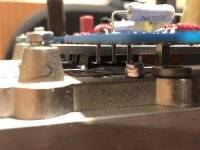
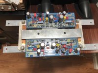
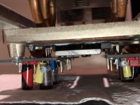
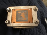
The attached pictures are my Alpha20 modules mounted opposing each other so two mosfets are on each cpu cooler. Aluminum flat stock is the holding clamp down the middle. Attachment points to the coolers are drilled/tapped in the aluminum that surrounds the copper pad.
These coolers can really dissipate heat well, with Noctua fans 130watts is no problem
6.5” - Total height (to tip of pipe)
3”w x 3”d x 3.25”h - aluminum finned size
3.75”w x 2.5”d - aluminum base
45mm x 63mm - copper mounting pad
The attached pictures are my Alpha20 modules mounted opposing each other so two mosfets are on each cpu cooler. Aluminum flat stock is the holding clamp down the middle. Attachment points to the coolers are drilled/tapped in the aluminum that surrounds the copper pad.
These coolers can really dissipate heat well, with Noctua fans 130watts is no problem
Attachments
Last edited:
Thanks, Vunce & X.
I'm just trying to figure out how those dimensions will fit in my case.
6.5" total height means I have to bolt them sideways ... unless I drill holes through the case top to take the pipes!
But that would be OK.
Certainly nice big copper mounting pad!
Andy
I'm just trying to figure out how those dimensions will fit in my case.
6.5" total height means I have to bolt them sideways ... unless I drill holes through the case top to take the pipes!
But that would be OK.
Certainly nice big copper mounting pad!
Andy
Last edited:
Hey X and everyone... have a bit of an issue here. I'm not getting any voltage on the Q12 side, the Q10 side is fine.
To date:
Checked to make sure on orientations
Went back over all parts and checked values.
Went over all soldering...
Both board led illuminate
Nothingsmoked
I do have one working board (Mono build) and I'm seeing some strange values in comparison to the working board. I know "strange values" doesn't help, but the values are in the area of Q11 and D4
Both test points to ground give me close to zero
Nothing on ground to Nvout
Pvout is at 29v
We can rule out Q12 as I dropped in the other supply with the same Q10 & Q12 in place and both sides work fine.
I put some power on it and got -30v on the collector of Q11 about 12mv on the base and zero on the emitter.
Help me with a test procedure on this if you would. I have a feeling it's Q11 & or D4, but I would like some help with diagnostics, before I order more parts.
Attachments
Last edited:
Hey X and everyone... have a bit of an issue here. I'm not getting any voltage on the Q12 side, the Q10 side is fine.
To date:
Checked to make sure on orientations
Went back over all parts and checked values.
Went over all soldering...
Both board led illuminate
Nothingsmoked
I do have one working board (Mono build) and I'm seeing some strange values in comparison to the working board. I know "strange values" doesn't help, but the values are in the area of Q11 and D4
Both test points to ground give me close to zero
Nothing on ground to Nvout
Pvout is at 29v
We can rule out Q12 as I dropped in the other supply with the same Q10 & Q12 in place and both sides work fine.
I put some power on it and got -30v on the collector of Q11 about 12mv on the base and zero on the emitter.
Help me with a test procedure on this if you would. I have a feeling it's Q11 & or D4, but I would like some help with diagnostics, before I order more parts.
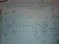
Sorry you are having trouble. you can help us diagnose by measuring the voltage (relative to GND) of each node of interest on the circuit. Write those by red pen on a printed out schematic and take a photo of schematic and post it here. Also, a closeup detailed photo of the board from a few angles so we can see components will be helpful.
By nodes of interest, I mean voltages on each 3 legs of the two transistors, voltages at C16 (negative pin), rail voltage at C14.
Having no voltage and no smoke means that the big BJT is not turning on. It is probably still good. So this may be a bad Q11 or incorrect part for Q11 or Q11 installed backwards, or a bad value on one of the resistors R10/12/15/16/18. A bad (open) diode won't hurt as it is there for protection, a shorted diode will smoke. But if unsure, pull it out and test it. A bad pot RV2 (open circuit) will also prevent this from working. Finally, double check the pinouts of Q12 from the PCB to the actual transistor. There are 3 wire, 4 pads, and two connectors - lot's of room for a mistake or maybe the wiring diagram for the connectors might be bad. Are you sure you an NPN there (TTC5200 or 2SC5200)?
Since I have a good working SLB I dropped it in with the same Q10 & Q12 and it worked perfectly, so we can rule out Q12 as a problem. Also, the orientation is okay on Q11 and verified the correct part. I did measure the values on Q11 on both the bad and good board.
RV2 is okay as well. All resistor values verified, but not removed and tested.
I get -30V on the collector and a few mV on the base and nothing on the emitter.
I pulled Q11 and tested it I get PNP hFE 215 Uf=608mV
RV2 is okay as well. All resistor values verified, but not removed and tested.
I get -30V on the collector and a few mV on the base and nothing on the emitter.
I pulled Q11 and tested it I get PNP hFE 215 Uf=608mV
Attachments
Last edited:
- Home
- Group Buys
- The SLB (Smooth Like Butter) Active Rect/CRC/Cap Mx Class A Power Supply GB