... [in a power supply CRC filter] the resistors themselves dissipate enough power to get pretty toasty.
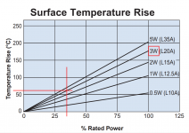
Although resistor manufacturers publish datasheets, few people read them. Which is too bad, because then there would be less angst and surprise when dissipating one watt in a 3 watt rated resistor produces a very hot booboo device. If the datasheet curves are accurate, thermal resistance theta (degrees C per watt) is constant; the curves are straight lines of constant slope, passing through the origin.
Oh and if you dare to dissipate 3 watts in a "3W" resistor, the resistor body will be 175 degrees C above ambient according to those curves. Hot enough to make the PCB turn brown. Hot enough to melt 63/37 solder!
_
Attachments
Last edited:

Which “people” are you referring to? We are using KOA Speer non inductive cement filled rectangular metal plate 5W resistors. A pair of 0.1ohm in series passing 5A is dissipating 2.5W ea - well under rating. This has all been sorted out with the verification build on the single rail.
Data sheet is page 211:
http://koaspeer.com/pdfs/brochures/KOA_Catalog_2017.pdf
Data sheet is page 211:
http://koaspeer.com/pdfs/brochures/KOA_Catalog_2017.pdf
Just referring to resistor buyers / resistor users who don't bother to read resistor datasheets.
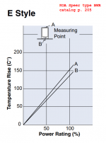
I couldn't find a temperature-vs-dissipated_power graph, or a theta spec, for the BPR resistors on page 211 of that KOA Speer catalog. But the previous resistor in the catalog, type "BWR" on page 205, looks physically very similar and I was able to find its graph, copied below.
If using a BWR resistor rated 5W, dissipating 2.5W in it will result in a temperature rise of 65 to 75 degrees C above ambient, depending on whether you measure at the bottom {which cooks the PCB} or the top {which burns people's fingertips.} Add the room ambient air temperature (~ 24C) and you're close to the boiling point of water.
It sounds like you have already investigated this, using either fingertips or thermometers, and deemed the resistor temperature acceptable. If so, congratulations. Too many people fail to do this, and receive a high temperature surprise early in the production of assembled units within chassis. The unhappiest surprise is when these folks operate a resistor "within rating" and yet it melts its own solder.
_
Attachments
Last edited:
It's definitely not something you want to grab with your fingers when it is running, but doesn't melt its own solder at least and we are giving it room for air flow. If folks are concerned about keeping temps low, use four 0.22R in series parallel and dissipation will be about 1.25W each for maybe 65C temps.
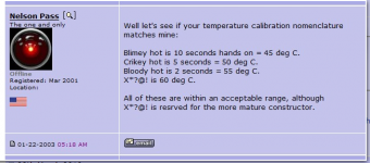
Here is a screen grab made by diyAudio member "ZenMod" sixteen years ago (!)
Somebody asked Nelson Pass, "When you touch various places on a Class A amplifier (heatsink etc), what physical sensations correspond to different temperatures?"
or some question like that.
NP replied, "Count seconds and see how long you can maintain contact before the pain becomes unbearable", and then he gave this handy table, attached below.
_
Attachments
A suggestion, as per the layout on post #12,
If you moved the LT4320 between the 2nd and 3rd fet (ie. move the first fet into old position of the LT 'around the corner' and so on...) the control tracks would be shorter and more uniform - same with the -ve rail - not sure where you'd fit the 1uf C5 & C6.
I see the board layout is 142 x 100mm, yes? I struggle a bit with the black background (not as young as I used to be!)
I think in the current layout, Jhofland is trying to keep the loop area for the high current flow as small as possible to reduce emitted EMI. Putting the LT4320 in bewteen the FETs would improve symmetry of the gate control traces, but that is secondary to minimizing generation of noise from large ripple currents around the MOSFETs.
For the same reason, the SMT implementation also has the LT4320 mounted off to the side:
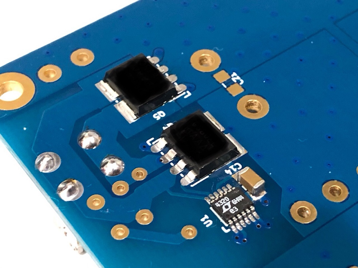
The SMT version is so much more compact.
For the same reason, the SMT implementation also has the LT4320 mounted off to the side:
The SMT version is so much more compact.
Sorry, don’t understand what you are asking about donuts and caddocks?
James is probably talking about adding pads (donuts) for Caddock resistors.
MP930-0.10-1% Caddock | Mouser India
30W in TO-247. Since the resistors are nearly at the extreme edges of the PCB, it might be convenient to locate TO-247 resistors so that they can be mounted flat horizontally on the bottom Aluminium plate or some heatsink, etc.. Just an an option....
Also , if the space permits, Dayton and HTR have non-inductive 10W resistors in 10mm wide x 50 mm long package . These can be paralled one on top of another for 20W capability with adequate space in between. Holes below these also help with cooling.
Here is what I did for my Tarkus X-over.
just 2c.
regards
Prasi
Attachments
Last edited:
They shipped from board fab house 2 days ago, I won't get for maybe 4 more days. The GB is still a go of course. Once I verify that this layout works and there are no mistakes, I will order the production boards. It takes more time and work this way, but in the long run is much better for people building it to make sure it is frustration free.
The single rail boards were part of an integrated amplifier that is not public release. Maybe Jhofland could make one of these is enough interest.
Thanks for replying. Some single positive rail boards would be good to try in my MoFo project if some could be made available (even gerbers so I could get some boards fabricated)?
I would also like to add my name to the GB list for the dual rail boards (2 boards).
- Home
- Group Buys
- The SLB (Smooth Like Butter) Active Rect/CRC/Cap Mx Class A Power Supply GB