Yes I have these in stock if you don’t mind using a small stamped aluminum heatsink vs the large PCB mounted one.
Firstly, major kudos for putting a low ripple, single rail PSU option out there. I recognise that bipolar is the best way to go but you can't always dictate design, so it's good to have a quality alternative.
Cutting to the quick (and apologies if this is obvious from prior detail), I gather that I'd need to allow for a 4V drop to account for the cap multiplier. So, if I've got a 24V DC application, such as a many of the First Watt designs, I gather I'd need to spec a transformer with 20-21 VAC secondaries, wouldn't I?
Apologies, if this should be obvious but I'd prefer minor embarrassment up front over a delivery disappointment - what's the best way to source a board with the on-board heat sink capability? GB here or an order over at the Etsy store?
Cheers

On a Class A amp, the current flow normally causes the transformer nominal zero load voltage to sag. Some trafos more than others depending on manufacturers or VA rating.
I have found through trial and error that the Antek 3222 (300VA) 22v provides about the right 24-25vdc rail under a 1.3A bias current load typically used on Pass 25w amp designs. This has been verified to work on my M2X as well as member SLk23’s M2X. Just one 300VA trafo is enough
The way to estimate the trafo rating is decide what voltage you want under load, say 24v. Add 3v for cap Mx dropout, add 5v for sag, so 24v +8v is 32v. Divide that by 1.4 and that’s the zero load rated AC voltage. 32/1.4=22.8v and so 22 is the closest one.
Hope that helps.
Last edited:
Here is the manufacturer's datasheet of the Antek AS-3222 transformer. It says that when the transformer's output current is 16 amperes RMS, the output voltage sags 2.1 volts below its value at zero-load.
I think you might also want to include peak-to-trough ripple magnitude in your headroom calculation, since the final output voltage is determined by the troughs not the peaks. The smoothed output must be less than or equal to the trough voltage; if it were higher then ripple would appear at the bottom of every trough.
Ripple magnitude is a function of load current, capacitance value, mains frequency, and ESR. You could dream up an equation which calculates ripple, and run some tests to find out whether it matches the ripple waveforms seen in PSUD2 or LTSPICE.
Those specs are highly optimistic and plain wrong based on my experience. I have about 24 Anteks in my donut collection. Don’t get me wrong, they are a great value and available in 2v increments in stock - unmatched by any other supplier. But they sag 3-4v sometimes 5v under typical loads. I always “buy up” now. The 400VA 18v Antek with a Pass F6 CRC gives me barely 22v. I would get a 20v one next time if not using cap Mx.
In my experience, Antek's transformers meet or exceed their datasheet specs in all cases.
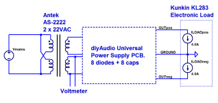
Just now I rigged up the experiment shown below. An Antek AS-2222 transformer (datasheet) operating from US mains, feeds a diyAudio Universal Power Supply PCB (link). The two DC output voltages from the Universal PSU, are connected to a two channel electronic load. I ran the experiment twice: once with the electronic load disconnected from the PSU, and again with the electronic load connected and pulling 4.0 amperes per channel. Here is my measured data, taken just 20 minutes ago:
The transformer's output voltage, going from (no-load) to (2 x 4 amps DC load), exhibited a "sag" of 2.18 volts, right in line with the datasheet numbers.
A few things to note:
~
Just now I rigged up the experiment shown below. An Antek AS-2222 transformer (datasheet) operating from US mains, feeds a diyAudio Universal Power Supply PCB (link). The two DC output voltages from the Universal PSU, are connected to a two channel electronic load. I ran the experiment twice: once with the electronic load disconnected from the PSU, and again with the electronic load connected and pulling 4.0 amperes per channel. Here is my measured data, taken just 20 minutes ago:
Code:
     Load Current    Voltmeter reading (Vsecondary)
     ==============================================
          0 amps           22.44 VAC
        4.0 amps           20.26 VAC
The transformer's output voltage, going from (no-load) to (2 x 4 amps DC load), exhibited a "sag" of 2.18 volts, right in line with the datasheet numbers.
A few things to note:
- This is a 200 VA transformer
- Output DC current is 4.0 amps, about 54% greater than the DC draw of a First Watt 25 watt Class A amplifier (2.6 amps)
- I am measuring at the transformer secondary, the same way Antek measures
~
Attachments
Last edited:
Well, people can either go by what Antek says and not get the voltage they need coming out of the SLB, or they can get the AS-3222 like I did, and like SLK23 did, and find that it gets them a solid 25v *at the amp*.
xrk971, thanks for running through the key details.
Experience counts for me.
What are your thoughts on this point?
... what's the best way to source a board with the on-board heat sink capability? GB here or an order over at the Etsy store?
The reason why the SLB produces disappointingly low DC voltages *at the amp* is: you have omitted peak-to-trough ripple when computing the in-to-out voltage drop. Antek is blameless, which you can easily verify by measuring the AC voltage of the transformer secondary under load. Don't measure anything downstream of the transformer, measure the transformer itself. You'll get the same number they print on their datasheet. They didn't lie.
Then you'll realize that the input to SLB is as-expected but the output from SLB is lower-than-expected. Luckily a calibrated two channel oscilloscope can show you why. LTSPICE can also show you why, possibly with less effort.
Then you'll realize that the input to SLB is as-expected but the output from SLB is lower-than-expected. Luckily a calibrated two channel oscilloscope can show you why. LTSPICE can also show you why, possibly with less effort.
The reason why the SLB produces disappointingly low DC voltages *at the amp* is: you have omitted peak-to-trough ripple when computing the in-to-out voltage drop. Antek is blameless, which you can easily verify by measuring the AC voltage of the transformer secondary under load. Don't measure anything downstream of the transformer, measure the transformer itself. You'll get the same number they print on their datasheet. They didn't lie.
Then you'll realize that the input to SLB is as-expected but the output from SLB is lower-than-expected. Luckily a calibrated two channel oscilloscope can show you why. LTSPICE can also show you why, possibly with less effort.
Mark, we (jhofland and Aksa) modeled the cap multiplier and CRC of the SLB in LTSpice and a dedicated PSU design package, and yes, the peak to trough ripple was accounted for, had you bothered to read the thread rather than to assume we blindly made the design, and making comments like the “disappointingly low” voltage. We all know that a cap Mx design will have dropout - it has to have it in order to have headroom to cover the peak to trough output ripple at 4.35A. No one is disappointed by the fact that a cap Mx has 3v of dropout in order to achieve 1mV ripple! Our simulations were also necessary to calculate the ripple current to spec the capacitor ripple current rating and R value in the CRC.
I am not blaming Antek on this design - even before using cap Mx, their DC levels at the amp, under Class A loads always left me wanting and regretting my choice of going with their rated voltages. As I said, on a bog standard Pass F5 to F6 CRC PSU, an 18v Antek gives no more than 22v at the amp. 2v less than design specified for 24v. Nothing to do with SLB’s cap Mx.
On your M2X with 18v Antek, what is your voltage at the amp? If you are happy with 22v, fine. I would like more headroom to hit the maximum power. 2v off the top is a big difference. Hence I suggest getting a higher rated voltage trafo than what might be suggested from Antek’s specs.
Before you come back to berate the SLB, do us all a favor and measure your DC input voltage at the amp, and show us the OScope screen shot of the ripple. I bet it’s 22v and about 120mV p-p. For someone who has not already bought an 18v Antek and DIYA universal PSU, simply choosing a 22v Antek (same price) and using the SLB, can now give you 25v rails and 1mV ripple. Easy choice as to which PSU and trafo voltage I would go with.
Last edited:
Every Antek I've ever measured, met its datasheet spec. If your post-Antek circuitry needs or wants more input voltage than what Antek guarantees on their datasheet, then either buy a higher voltage transformer or redesign the post-Antek circuitry. But don't blame the lower-than-desired DC voltage final output, upon the transformer failing to meet its spec.
Start with your testbed PSU that includes an Antek and a SLB board and a load resistor. Use a 4.5 digit DVM to measure the Antek AC secondary voltage (a) with no load on the DC outputs; (b) with your standard load on the DC outputs. Subtract these two numbers and voila, you have measured the transformer "sag". The analogous setup to attachment 1 of post #445. You are measuring the Antek and nothing else.
Start with your testbed PSU that includes an Antek and a SLB board and a load resistor. Use a 4.5 digit DVM to measure the Antek AC secondary voltage (a) with no load on the DC outputs; (b) with your standard load on the DC outputs. Subtract these two numbers and voila, you have measured the transformer "sag". The analogous setup to attachment 1 of post #445. You are measuring the Antek and nothing else.
xrk971, thanks for running through the key details.
Experience counts for me.
What are your thoughts on this point?
Please place order on Etsy shop - I am handling GBs via Etsy so that the logistics are much easier when it comes to order fulfillment. The new SLB GB boards should be arriving today.
SLB is here:
Smooth Like Buttah SLB Class A PSU | Etsy
The pcbs were supposed to arrive today but are held up in customs (probably for the new 25% tariff on goods from China). This might end up being quite a bill that was not anticipated.
Well, apparently trade wars are a good thing. Go figure.
At least it's not 5G tech or we'd all be looking at a whole lot of nothing.
Hopefully, you sail under the radar.
My AS-4222 - 400VA 22V transformer with 119Vac mains gives me +/-27Vdc at input of my F4 drawing ~5.5A total (~1.4A each rail).
What are some recommend methods of mounting the toroid on it's side? I am thinking of just bending some flat stock Al bars 90 and drilling/tapping holes.
What are some recommend methods of mounting the toroid on it's side? I am thinking of just bending some flat stock Al bars 90 and drilling/tapping holes.
Attachments
Shawnstium, there is a company in Maryland USA who sells two kinds of brackets for vertically mounting toroidal transformers. Here is a page on their website which shows the options
Toroid Corporation > Products > Mounting & Hardware
I have done business with them and am pleased with their product and service.
Toroid Corporation > Products > Mounting & Hardware
I have done business with them and am pleased with their product and service.
My AS-4222 - 400VA 22V transformer with 119Vac mains gives me +/-27Vdc at input of my F4 drawing ~5.5A total (~1.4A each rail).
What are some recommend methods of mounting the toroid on it's side? I am thinking of just bending some flat stock Al bars 90 and drilling/tapping holes.
Unless you really want to fabricate something the L bracket from toroid.com seems like a good solution.
Originally I made an L bracket from some 0.063" sheet aluminum I happened to have. It was a bit too springy so I made a U bracket from the same material. One thing I didn't anticipate with the U bracket was that the through bolt needs to be insulated from the bracket (I used some nylon bushings). When the bolt was in electrical contact with the bracket it got very hot from induced currents.
Last edited:
Working in IT has its perks. I have collected many old brackets for mounting equipment in 19" cabinets. Most of them are very sturdy - especially the old Nortel/Avaya ones - and work a treat. Holes are all there especially on the short L-base where there are two - bolts solidly to the base.
I just got word from DHL that the boards will be delivered by end of the day today, after a 4 day holdup at customs. It will be good to ship out all of these SLB’s. Looks like the board is already positively contributing to several Class a projects with clean smooth power.
- Home
- Group Buys
- The SLB (Smooth Like Butter) Active Rect/CRC/Cap Mx Class A Power Supply GB