Thanks for confirming this. I have now managed to get the parts off. Will add nylon washers and non conductive thermal pads as per your advice.
I think I’m going to reorder some new transistors as I feel I’ve subjected them to too much heat as getting them off was a real challenge. This time round I will forego using Loctite and will nut and bolt them instead so removal will be easier should I screw up again. I was concerned that I’d end up lifting a PCB trace but is seems those boards are very well made and very rugged, kudos on a quality product.
I think I’m going to reorder some new transistors as I feel I’ve subjected them to too much heat as getting them off was a real challenge. This time round I will forego using Loctite and will nut and bolt them instead so removal will be easier should I screw up again. I was concerned that I’d end up lifting a PCB trace but is seems those boards are very well made and very rugged, kudos on a quality product.
Hi STUNTfingers,
Great to hear it was basically an easy fix, tracking down a solder bridge somewhere can get very frustrating!
(My first Yarra had one )
)
Please make sure to use a nylon/plastic shoulder washer to attach the transistors to the heatsink, not a flat washer. There could still be a chance the threads on the fasteners can touch the metal tab and short.
Great to hear it was basically an easy fix, tracking down a solder bridge somewhere can get very frustrating!
(My first Yarra had one
)Please make sure to use a nylon/plastic shoulder washer to attach the transistors to the heatsink, not a flat washer. There could still be a chance the threads on the fasteners can touch the metal tab and short.
Attachments
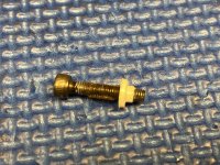
Your BJTs are probably fine because the short went from collector to ground and not through the junction. But they are inexpensive and may be wise to replace. A good practice is to always use a conductivity meter (beep mode) to check the tab of a transistor or mosfet to make sure it’s not conducting to the heatsink. Rarely is this ever done on purpose. Sometime a small metal burr in the threaded hole can poke through the silicone sheet and short out a transistor. This happened to me once and blew the BJT and the driver transistor. It was a mess to replace.
Thanks X and Vunce, much useful advice as always!
I've just ordered some nylon shoulder washers from eBay as well as some hardware to fix them in place.
Re checking conductivity I will certainly do this in the future, today was a good lesson. I've spent the best part of 8 hrs checking the board looking for the fault, learning about NPN vs PNP and re reading this thread looking for clues. As a complete amateur when it comes to board stuffing and building something like this it all seemed to be going too well...
Hello,
I have a Yarra with Melbourne boards, and I want to try a more transparent volume control than what I have in there. I have a spare Gold Point stepped attenuator but it has an input impedance of 100k. Would such a high input impedance have any drawbacks in this circuit?
Thanks,
Alan
I have a Yarra with Melbourne boards, and I want to try a more transparent volume control than what I have in there. I have a spare Gold Point stepped attenuator but it has an input impedance of 100k. Would such a high input impedance have any drawbacks in this circuit?
Thanks,
Alan
X, Hugh, others,
Referencing to posts 1187-1190 in this thread, I see that the Hakuin has an overall gain of about 11-12 dB. My plan is to use the 2SK170BL/2SA1837 version but I would like to see if overall gain of the board can be lowered to 5-6dB to use in my M2X amplifier.
Thanks,
Anand.
Referencing to posts 1187-1190 in this thread, I see that the Hakuin has an overall gain of about 11-12 dB. My plan is to use the 2SK170BL/2SA1837 version but I would like to see if overall gain of the board can be lowered to 5-6dB to use in my M2X amplifier.
Thanks,
Anand.
You can certainly install two new components, a series RC circuit, between JFET drain and positive supply. This will lower the gain to any value you like without changing any bias voltages or DC currents. {why? because no DC current flows through a series RC circuit. why? because of the C!} Whether this tweak changes something else that you find sonically significant, and whether such a change is beneficial or detrimental, is not known to me. Try a quick experiment to find out!
_
_
Last edited:
Volume pot boards
Hi all,
I'm working on another project in which I'm using Alps RK097 pots. I want to use the board that comes with the Yarra kits. I have two, but need one more.
The board I need is labeled, R211, where the pot mounts. Now if someone had 4, I'll take them too, because I mistakenly double ordered the pots
PM me if anyone has one or more and would be willing to part with them.
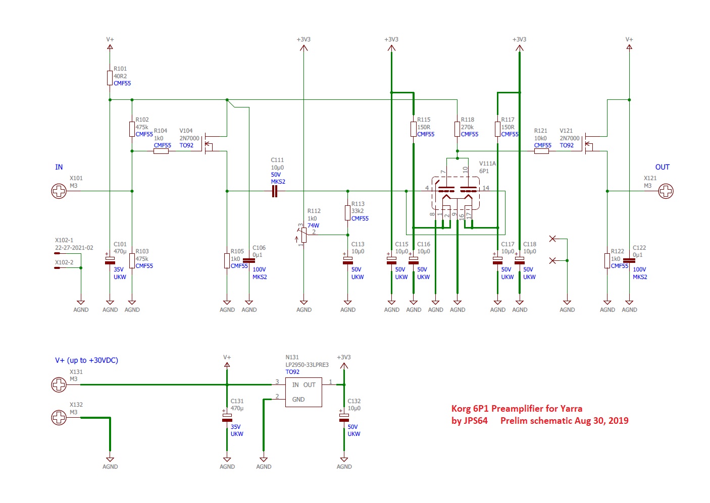
It’s based on the design described here:
Nutube 6P1 Buffer PCB
Gain is 6x (15.6dB) and supply is 12v, so I would imagine max output is probably maybe 10vpp or 3.5vrms? But I would keep it well below that to keep distortion down. Maybe 2vrms?
Nutube 6P1 Buffer PCB
Gain is 6x (15.6dB) and supply is 12v, so I would imagine max output is probably maybe 10vpp or 3.5vrms? But I would keep it well below that to keep distortion down. Maybe 2vrms?
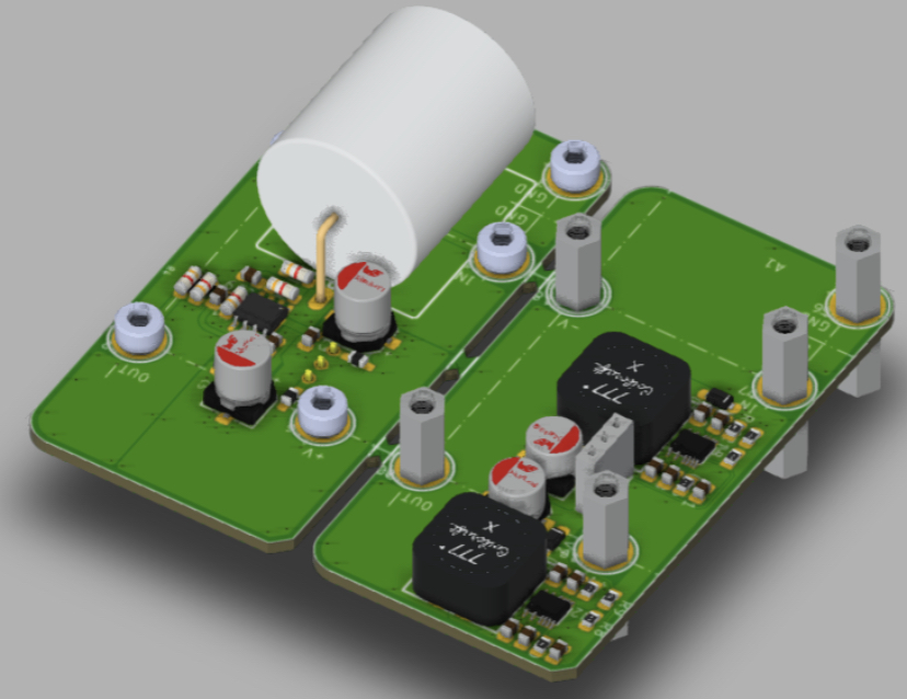
It might work but probably not optimal as designed. If someone could redo the spice simulation and redo the output MOSFETs it could work. It just takes some design time and verification with a test build. That’s where your DIY abilities come in.
If we make the V+ input say 24v, the voltage regulator can still reduce that to the amount needed to power the Nutube 3.3v, the pot would have to be adjusted differently for a grid voltage of 12v but the drain on the output MOSFET could be higher. This might allow more swing. It just needs to be tested. It might be as simple as that. If anyone has ability to measure what the maximum output swing is that would be great. I don’t have it setup currently to try out.
You could probably get 18vpp with 24v input. That’s about 5w rms into 8ohms.
Last edited:
Under development: A new 22dB gain 50mA capable DC coupled preamp module capable of +/-35v output with built DCDC PSU. We are planning on using this in the LuFo amp.
OPA454 Front End for LuFo Amp
OPA454 Front End for LuFo Amp
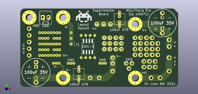
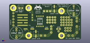
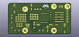
Member Puijkh made a slick little Yarra/M2X format Experimenter’s breadboard:

More here:
What’s On the Bench Tonight (OBT)
This could be really handy.
More here:
What’s On the Bench Tonight (OBT)
This could be really handy.
Attachments
Last edited:
I have an M2X/Yarra format breakout board that is ideal for experimenting or making a compact preamp if you want to use your own PSU.
M2X/Yarra Format Breakout Board

Example of it being used to make a standalone ACP+ preamp:
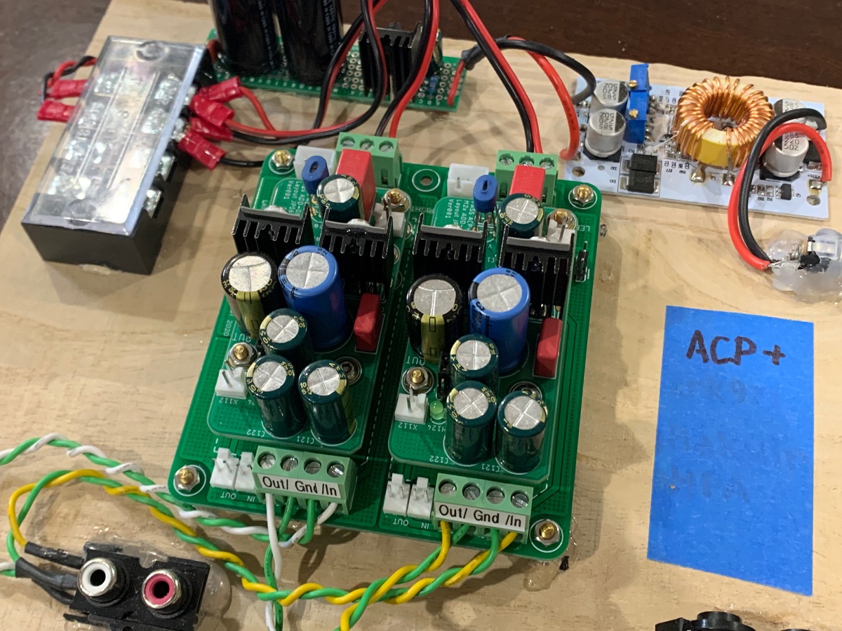
Your choice of screw terminal blocks or Molex KK/JST connectors - you can go wild!
M2X/Yarra Format Breakout Board
Example of it being used to make a standalone ACP+ preamp:
Your choice of screw terminal blocks or Molex KK/JST connectors - you can go wild!
I like your breakout board. Since I am doing monoblocks, I would probably end up making a board for each channel. I was thinking it would be handy to use before an F4 or a MoFo which don’t have connections for the Yarra boards. I am trying to avoid a separate preamp. Just run directly from my DAC which has volume control and basic preamp capability.
I started looking at the Yarra boards after I went back to finishing up my M2X. I noticed the Melbourne card I had bought from the GB. Found that there were quite a few more available. I saw that the Korg one just got listed on your store. I like the modular concept for amps as well as preamps.
I started looking at the Yarra boards after I went back to finishing up my M2X. I noticed the Melbourne card I had bought from the GB. Found that there were quite a few more available. I saw that the Korg one just got listed on your store. I like the modular concept for amps as well as preamps.
Last edited:
Here is new +/-35v output OPA454 Yarra format front end:
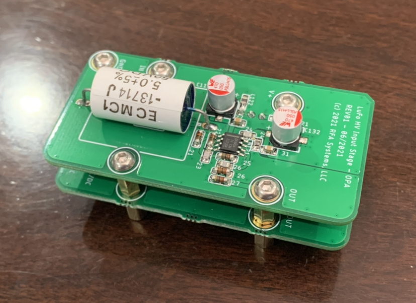
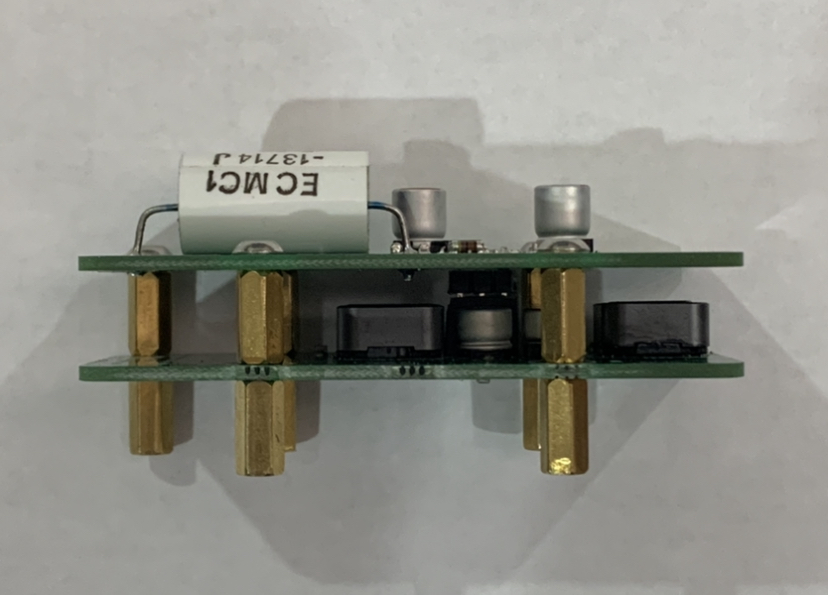
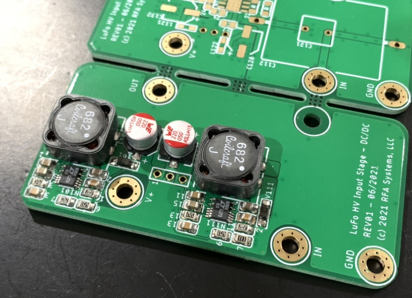
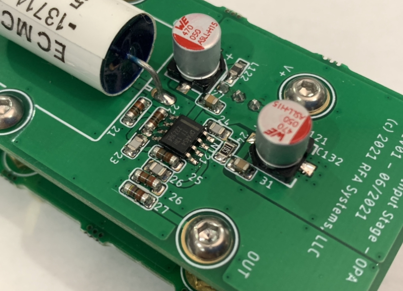
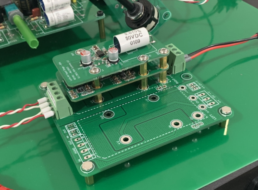
Tested on the LuFo amp. Sounds super. Can be powered off 12v wall wart as shown here or amplifier main positive rail (28v or higher). Provides 22.4dB gain and up to 125mA current, and 0.0008% THD spec.
Tested on the LuFo amp. Sounds super. Can be powered off 12v wall wart as shown here or amplifier main positive rail (28v or higher). Provides 22.4dB gain and up to 125mA current, and 0.0008% THD spec.
Last edited:
- Home
- Group Buys
- The YARRA Preamplifier/HPA for Melbourne DB Group Buy