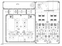
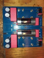
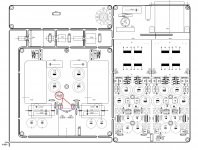
Hi, here is my build of yarra-nutube.
There is also some distortion charts vs bias.
It is for sure some tube harmonics, it sounds fat, really fat, my cholesterol level rise every time i listen to it.
Still i do not recommend it more than 1V rms output. Bellow 1V it sound devilish. More than 1V harmonics go crazy.
PS. It has small hiss
There is also some distortion charts vs bias.
It is for sure some tube harmonics, it sounds fat, really fat, my cholesterol level rise every time i listen to it.
Still i do not recommend it more than 1V rms output. Bellow 1V it sound devilish. More than 1V harmonics go crazy.
PS. It has small hiss
Attachments
-
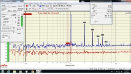 2.5v bias 1v rms out.jpg387.6 KB · Views: 284
 -
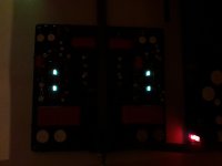 20191206_171812.jpg177.8 KB · Views: 164
 -
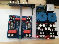 20191206_160554.jpg252.8 KB · Views: 171
 -
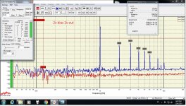 2v bias 2v out.jpg383.3 KB · Views: 263
 -
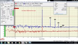 2v bias 500mvrms out.jpg384.3 KB · Views: 260
 -
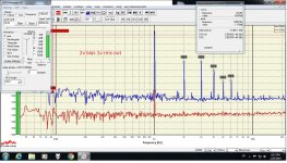 2v bias 1v rms out.jpg383.9 KB · Views: 275
 -
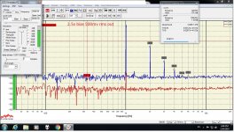 2.5v bias 500mv rms out.jpg380.3 KB · Views: 283
Nice,very nice!Hi, here is my build of yarra-nutube.
There is also some distortion charts vs bias.
It is for sure some tube harmonics, it sounds fat, really fat, my cholesterol level rise every time i listen to it.
Still i do not recommend it more than 1V rms output. Bellow 1V it sound devilish. More than 1V harmonics go crazy.
PS. It has small hiss
I like it!

I like the Dr Jordan software too!
Thank you too Vunce, your Mouser list helped me a lot.
I made some measurements on my system. My DAC outputs 1Vrms if i dial -11dB. When i insert the preamp, i dial -27dB for 1Vrms preamp output. So the gain of preamp is about X8(16dB). I normally listen at a dial of -45dB(125mV preamp output). A dial of -33dB(500mV preamp output) sound pretty loud on my system.
After some listening sessions, i can say that it sounds beautiful, rich and textured, a joy to listen to.
My 22v Talema’s are installed, but I did test a Talema 70064K (18v) transformer with the Qmodo jig for the Yarra and came up with:
Cs: 0.15uF
Cx: 0.01uF
Rs: 24R
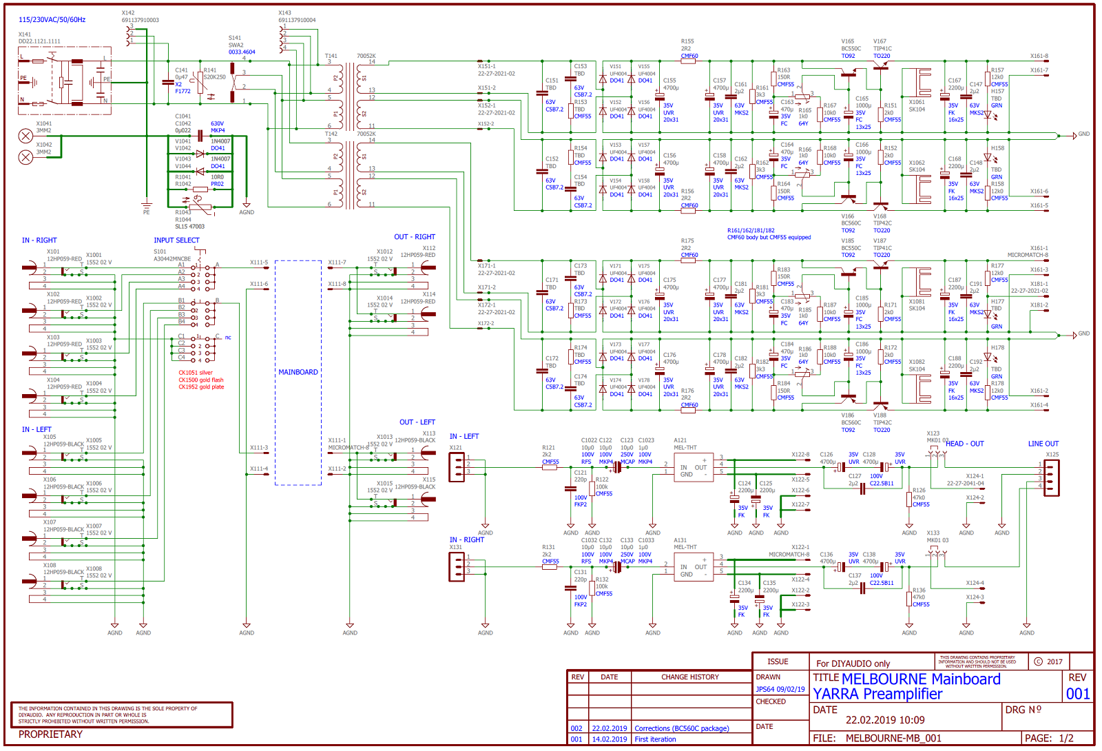
Yarra snubber location ID’s
Cs = C153,154,173,174
Cx = C151,152,171,172
Rs = R153,154,173,174
So the noob that I am, I used the snubber values that Vunce's BOM, for his 22v Telema. RS: 51R1 etc. I'm using the 18v. 70064's. The quoted values above should get close, correct?
I've missed a lot in the last few weeks, and see that some remork is in order. Although every thing seems to be working fine. No hum has been added to the system that I can tell. No pops on start-up... forgot to turn off the amp after a session, and then fired up everything in the correct order... oops. No pop, is good. I'm not going to be using this Yarra as a HPA.
I don't have all the fancy test gear that some of you all have. So I'm trying to decide what needs to be changed. It seems like R126/136 change to 1K is merited.
Thanks guys!
@T
Edit Nov 18. 2019: change R126/136 from default 47k to 1k in order to reduce the output DC offset decay time when using cap coupled (not DC) output. Also, make sure you power the Yarra on first before the power amp. And when shutting down, power off the power amp first before the Yarra. This will prevent turn on/off transients from reaching your amp.
Alternatively, if using Yarra as purely a preamp (no headphone amp use), replace C126/128 and C136/138 with 22uF each. Leave the bleed resistor at 47k and this should provide adequate bass response and only a 0.3s time constant.
I have a question here with regards to the circuit for headphone. Since I'm not using headphones, C126 C128 C136 C138 can be any old 10uF cap I have lying around right? What I'm getting at is those caps shouldn't make any sonic difference when not using the headphones. Is this true or what am I missing? I have a couple Vcaps lying here, I am going to put in for C123-C133. Is there any benefit to having good caps in 126-138 as well?
JT
JT
Last edited:
Folks, when asking a specific technical question where you cite a component number on a schematic, if you wouldn’t mind posting the image of that schematic in your question it would save me time and I can answer you right away.
So the question is C126 to C138. If not using headphones, what kind of caps to use here?
These are the main audio output coupling caps. They are important for sound quality. I would use either Nichicon Muse or Elna Silmic II. 100uF back to back or single NP 47uF. On the bypass film cap use the best you have, MKP minimum and nice polycarbonate or metal foil in oil etc.
Last edited:
Will do on the schematic, we do appreciate you taking the time and do not want to make it harder/ more time consuming on your part.
In post 998
You refer to these caps for preamp use only and state that back to back 22uF will be fine and in the next post, Since they are in series this is about11uF and in your next post 999 you state, "Or, if one prefers, a single 10uF bipolar electrolyic or a nice film cap (MKP, MKS, or boutique silver foil in oil, etc) of your choice"
SO I am a little confused here, if using only one cap + to + is the value 10-11uF or 47-50uF and to the bypass cap/s per the schematic you posted are C127 and C137 correct?
My thought now is to use the 10uF VCaps + to + or solo for C126+C128 and C136+138 and the BOM 2.2Wima for bypass.
I'm going back and learning circuits and reading books to get up to speed, so please be patient while I get there.")
Thanks
JT
In post 998
You refer to these caps for preamp use only and state that back to back 22uF will be fine and in the next post, Since they are in series this is about11uF and in your next post 999 you state, "Or, if one prefers, a single 10uF bipolar electrolyic or a nice film cap (MKP, MKS, or boutique silver foil in oil, etc) of your choice"
SO I am a little confused here, if using only one cap + to + is the value 10-11uF or 47-50uF and to the bypass cap/s per the schematic you posted are C127 and C137 correct?
My thought now is to use the 10uF VCaps + to + or solo for C126+C128 and C136+138 and the BOM 2.2Wima for bypass.
I'm going back and learning circuits and reading books to get up to speed, so please be patient while I get there.
Thanks
JT
Last edited:
You can vary the values but try to keep the RC time constant such that it is at least one decade lower than the bottom frequency in bass you want to reach.
Let's assume you want 20Hz reach. So we need a time constant that is 10 larger than 1/20Hz or 5msec x 10 = 0.5 seconds.
If we assume that some amp input impedance loads are as low as 22kohm, then what is capacitance needed?
RC time constant T = 0.7 x R x C, solve for C
C = T/(0.7 x R) = 0.5 sec. / (0.7 x 22kohm) = 32uF
This is why I picked 100uF back to back to make a 50uF non-polar electrolytic.
Let's do a case where we want to drive 250ohm headphones.
C = T/(0.7 x R) = 0.5 sec. / (0.7 x 250ohm) = 2857uF (two back to back 4700uF make a 2350uF which is close)
But a big cap like that will need to be bled with something like a 680ohm to 1k resistors, or else the DC offset on the cap can take minutes to discharge and you will get a thump.
Discharge time if using a 680ohm bleed resistor is T = 0.7 x 680ohm x 2857uF = 1.36 seconds.
Hope that helps you rework it for a 10uF output cap.
Last edited:
Outstanding! I'm driving a J2, so that input is 100k from Papa, the speakers can go down to 15hz or there about, so that gives me a constant of about .83 secs and a discharge of about .33 secs.
A couple of questions, do I want to go up some on the 47k bleeder and also, since my caps are only 10uF, does the bypass cap value need to be changed from 2.2uf?
Thanks again for your time X
JT
A couple of questions, do I want to go up some on the 47k bleeder and also, since my caps are only 10uF, does the bypass cap value need to be changed from 2.2uf?
Thanks again for your time X
JT
More Questions
I have the Yarra and HPA done and have a rails of about 23-27v +-
A couple of things before I drop the 1st Melbourne on. Did I read something somewhere about a jumper needed on X123 and X133 pins 2-3 or the right most pins?
Again Preamp only.
Also, I'll be driving the J2 so what rails and what voltages should I set and what am I looking for at TP x1024 and X1023 on the Melbourne?
Also, I took your advice and have a 22uF Vcap C126-C128 and C136-C138 instead of the 10uF.
Thanks again X
JT
Attachments
Last edited:
Just look at the traces and you can follow what X123/133 does. Connect the inside pins with the middle pin (red) on X123/133 if you want to use the headphone output connector X124. If you want the output to go to the X211, which then goes to the Input Selector board/output RCA's, then connect the outside pins with the middle pin (blue).

Attachments
Grounding
I'm building now and have been speaking with X during the process. I ran into the ground deal Meanie discusses, see the first page with link. He replaced all the brass standoffs with poly ones. I don't think this is needed, but the one he shows as the main ground from the PS absolutely needs to be poly or no standoff in that position.
I inspected and tested all standoff attachment holes and none of them are linked electrically to ground of any sort.They are in fact isolated from all traces and ground-planes. With the exception of the ground on the rear right pad, just to the right of the mains on the PS board, which is chassis grounded.
I'm typing this for us newbs out here. If you leave the brass standoffs in there, don't use them as a probe ground point when checking critical voltages on HPS or daughters, as there may be some small potential variation there.
If I have this wrong, X or V or anyone else, please set the record straight.
One last thing for some of the FNGs like me. It wouldn't hurt to PM some of the people you find most helpul and those that do much of the legwork for us. I'm sending them a couple Christmas bucks for all their help.
Thanks all!
JT
JT
Last edited:
That's very kind of you Thompsontechs! We try to be helpful because we want you to hear the beautiful sound that we hear. It is amazing what one can make with one's own hands that rivals some of the best commercial stuff out there in sound quality.
Happy Holidays!
The kindness resides with Nelson on down the line to all you, who make it possible, for those of us who don't have the money, and/or the skills to purchase/build. Ya, it's very cool to hit the local hifi and smile when I know my stuff sounds as good, or better than the stuff which cost more than my car.
Cheers!
JT
Yarra with Melbourne up and running, still have some odds and ends to finish up, but shes dead quiet, no trace of hum on either output, checked all inputs. Ran it for a couple hours into my Elekit 8600 and it was a sweet combo, but not where it's going to be. She will drive the F2 or M2X.
What are you guys running your rails at for the Preamp only version with Melbourne? Mine are sitting @ 24v right now.
I had a 25w Lightbulb on to check for problems, she lit-up and then dimmed, but didn't go out with one Melbourne... Hmm, pulled the power and inspected the board. Whoops, installed one of the caps wrong polarity. Another board saved by the bulb! Pulled the cap turned it around and all was well.
Thanks to all who have helped, esp to X and V. Now, on to the J2 which I have parts for. Tempted to do the M2X first as the load on one of my pairs of speakers are 4ohms. Hmmm decisions.
Last edited:
- Home
- Group Buys
- The YARRA Preamplifier/HPA for Melbourne DB Group Buy