Hello Otto,
Sure, it is also possible to produce just one chassis but the final cost will be higher.
There isn't a "real MOQ" as we can also produce a single chassis. The more are needed, the better the price we can make
If you have any other question feel free to write them in this thread so other members can read them too, I'll be happy to help")
Sure, it is also possible to produce just one chassis but the final cost will be higher.
There isn't a "real MOQ" as we can also produce a single chassis. The more are needed, the better the price we can make
If you have any other question feel free to write them in this thread so other members can read them too, I'll be happy to help
…
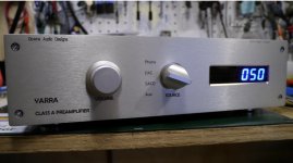
However, I missed having a remote volume control.
So, I decided to add a volume control module inside the existing case. The Muse control I used was a project by member meldano he created a couple years ago. Information on this project can be found here.
As most of you know, there is not much 'extra' space inside the Yarra. Getting everything to fit was a little challenging, but obviously doable. The module requires +-15V, and includes an onboard regulator supplying 5V for the micro-contoller and display. I decided to use a separate supply, with a small toroidal tranny under a DIY'ed faraday cage to help minimize noise.
The meldano project is available in SE output, or using 2 stereo boards - balanced as well. To attach the VC I used one of the small unused PCB included with Yarra kit. That was the simplest plug-n-play replacement and worked effectively.
The display is optional as well.
Below are some pictures of my install inside the Yarra, as well as the finished revised chassis. As you can see, a pretty tight fit of everything.
I polished off the mod with the front panel being 'redone' by FPE to support the display, and my input/ selection text.
With very limited testing in my system - using X's new class D amp, I've been impressed.
I can't hear any noise introduced by the controller, and the volume has 240 steps! One nice addition is, the project uses the ubiquitous Apple remote for volume up/down and mute. Very convenient.
Hi redjr
I’m about to buy the Yarra and want to make sure it ticks every box.
Your implementation - with the addition of Meldano’s Muse/ looks pretty well perfect …
https://www.diyaudio.com/forums/search.php?searchid=24746755
I’ve just checked, and the PCBs and microcontroller are still available
A couple of simple/ dumb questions -
“To attach the VC, I used one of the small unused PCBs included with the Yarra kit” - that was one of the daughterboards? I’d guess - the smallest one?
It’s available in “ available in SE output, or using 2 stereo boards - balanced as well” - for the Yarra, you bought the SE?
Your display looks * very professional
> is optional
A Diyaudio guy (Meldano) also supplied a display? (If not, do you recall where you got it?)
The custom hole in the thick front plate - hopefully/ presumably Modushop could do it? (for extra) so it’s all one purchase. I guess the display comes with mounts, so size the hole for the right match.
Much appreciated

Last edited:
Hi Xrk
Thanks for the confirmation.
And updating the Etsy
Imo having different/ changeable amplifier daughter boards are an excellent approach. …
Hifi design evolution: Not just the Yarra, who firstthought of that, first made interchangeable amps/ hifi core stages as modules?
Aksa Lender:
On commercial preamps you can say the DIP8 opamp socket used by many companies allows people to “roll opamps”. But for discrete preamp cores, I have not seen it anywhere else except by JPS64 first on the Aksa Lender preamp. That preamp had vertical cards for the cores. That was a single rail preamp so the daughter boards were single ended designs like the PCA, or just SMT variations of the same Aksa Lender topology. In Yarra, the format was adopted to match bolt pattern on M2X amp so that these cores could be used as front ends on the M2X. There is an extra bolt for ground on the Yarra, which would have to be connected separately for other applications.
The simple Aksa Lender (single rail version of Melbourne) preamp is still one of my favorite go-to designs for a preamp and I have adapted it as a board for the Yarra. I still need to build the verification as we just got the design from JPS64 a few weeks ago.
Last edited:
Hello Gianluca,
Thanks for chiming in …
I mainly mentioned MOQ as a partial pointer to the possibility that there may be enough interest for another Group order. But that’s probably extremely unlikely, so -
Naturally … As a very close/ starting point, ex VAT but before shipping, what would it be for one, exactly as it was?
If you have any other question feel free to write them in this thread so other members can read them too, I'll be happy to help[/QUOTE]
Thank you
Btw, for the design (and organisation) by JPS64 and his wife - a big thank you from me
I’ve only twice been involved in changing aspects of a CAD design, but “here’s hoping”. I hope this doesn’t sound niggly. (I’m a sometime designer of other bigger things)
After looking through this thread, a couple of useful changes -
One comment, echoed by some -
“I wasn't able to get the Alps or the TKD pot threaded to the front panel, after mounting the pots to the PCB adapter. Ideally the panel would be countersunk even more”
Some pots fitted/ without too much hassle, but to widen the options/ not have to be concerned, that sounds sensible. I don’t know much material was left in the original countersinking for the volume pot knob … could you suggest a deeper depth of countersinking?
You’ve probably now seen my post about a hole in the faceplate for a display. I don’t yet know its exact dimensions, but approximately how much extra would that be?
The back plate
- one said the rear I/O board “will also need some center support to avoid flexing”. … only one in 27, so not a * problem, but for such a first class amp - imo solid = good, especially if/ when swapping any * tight fitting leads -
what was the depth & material of the back cover?
- I saw that eg the MANLEY RCA phono jacks just fitted. My approach …
I recall when once looking at an amplifier case with Hugh Dean, seeing its very close sockets required extra care etc - while there was plenty of “spare real estate” he said something like “why don’t they simply space these a little more wide apart”. I agree
If the vertical gaps between the pairs of inputs and outputs, currently ? 5 ? mm were to be say 3 mm more; and the spaces between the four inputs were closer to the spaces between the outputs …
If that then encroached on the surrounding labels/ so the labels then would look not quite right, if it were a hassle to stretch the labels, I would fine with leaving those labels on the right hand size .. off.
Ergonomics over looks, “form follows function”.
Especially on the “working” I/ O side, out of sight, on the back …
on the front, it will still say YARRA in a nice, discreet size font
(To borrow an old phrase of Hugh’s)
Much appreciated
Thanks for chiming in …
There isn't a "real MOQ" as we can also produce a single chassis. The more are needed, the better the price we can make
I mainly mentioned MOQ as a partial pointer to the possibility that there may be enough interest for another Group order. But that’s probably extremely unlikely, so -
Sure, it is also possible to produce just one chassis but the final cost will be higher.
Naturally … As a very close/ starting point, ex VAT but before shipping, what would it be for one, exactly as it was?
If you have any other question feel free to write them in this thread so other members can read them too, I'll be happy to help
[/QUOTE]Thank you
Btw, for the design (and organisation) by JPS64 and his wife - a big thank you from me
I’ve only twice been involved in changing aspects of a CAD design, but “here’s hoping”. I hope this doesn’t sound niggly. (I’m a sometime designer of other bigger things)
After looking through this thread, a couple of useful changes -
One comment, echoed by some -
“I wasn't able to get the Alps or the TKD pot threaded to the front panel, after mounting the pots to the PCB adapter. Ideally the panel would be countersunk even more”
Some pots fitted/ without too much hassle, but to widen the options/ not have to be concerned, that sounds sensible. I don’t know much material was left in the original countersinking for the volume pot knob … could you suggest a deeper depth of countersinking?
You’ve probably now seen my post about a hole in the faceplate for a display. I don’t yet know its exact dimensions, but approximately how much extra would that be?
The back plate
- one said the rear I/O board “will also need some center support to avoid flexing”. … only one in 27, so not a * problem, but for such a first class amp - imo solid = good, especially if/ when swapping any * tight fitting leads -
what was the depth & material of the back cover?
- I saw that eg the MANLEY RCA phono jacks just fitted. My approach …
I recall when once looking at an amplifier case with Hugh Dean, seeing its very close sockets required extra care etc - while there was plenty of “spare real estate” he said something like “why don’t they simply space these a little more wide apart”. I agree
If the vertical gaps between the pairs of inputs and outputs, currently ? 5 ? mm were to be say 3 mm more; and the spaces between the four inputs were closer to the spaces between the outputs …
If that then encroached on the surrounding labels/ so the labels then would look not quite right, if it were a hassle to stretch the labels, I would fine with leaving those labels on the right hand size .. off.
Ergonomics over looks, “form follows function”.
Especially on the “working” I/ O side, out of sight, on the back …
on the front, it will still say YARRA in a nice, discreet size font
(To borrow an old phrase of Hugh’s)
Much appreciated
Redjr makes some nice boxes is all I can say.
Absolutely.
And with enhanced functionality
Last edited:
Aksa Lender:
… for discrete preamp cores, I have not seen it anywhere else except by JPS64 first on the Aksa Lender preamp.
The Lender had vertical cards for the cores. That was a single rail preamp so the daughter boards were single ended designs like the PCA, or just SMT variations of the same Aksa Lender topology.
In Yarra, the format was adopted to match the bolt pattern on the M2X, so the cores could be used as front ends on the M2X. There is an extra bolt for ground on the Yarra, which would have to be connected separately for other applications.
The simple Aksa Lender (single rail version of the Melbourne) preamp is still one of my favorite go-to designs for a preamp, and I have adapted it as a board for the Yarra. I still need to build the verification as we just got the design from JPS64 a few weeks ago.
I thought that the Lender was the first. …
so apparently/ probably a world first!

So it was a JPS64 “Eureka” step forward (probably following from discussions with you and or Hugh?) …
The whole can be greater than the sum of the parts
TOTAL KUDOS!!
Hi Otto,
You did some great research here for lessons learned from the chassis. I have since found some RCA jacks that are compatible with the Elecaudio RCA footprint and has smaller diameter nuts that will fit the chassis, as is. Vunce reminded me that the PCB back panel board has an orphaned ground pad on certain versions. So I need to get this sorted out to make sure the new batch has this issue fixed.
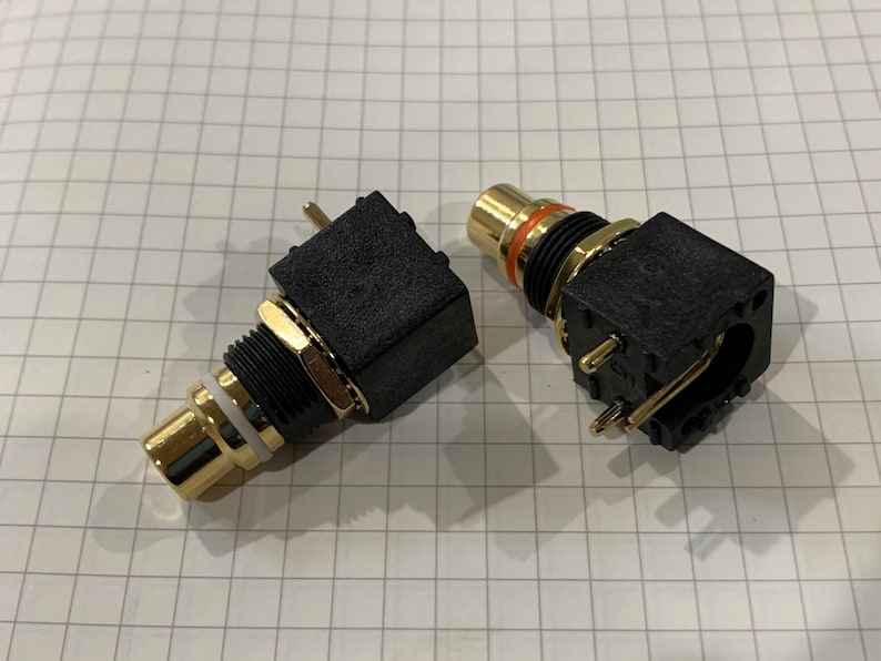
Here are the RCA jacks that would be compatible with Yarra. The pins can be adjusted for 90deg or 0deg orientation mounting. Note the very low profile nut vs the Elecaudio version.
Premium RCA jacks for BTSB/Yarra pair | Etsy
You did some great research here for lessons learned from the chassis. I have since found some RCA jacks that are compatible with the Elecaudio RCA footprint and has smaller diameter nuts that will fit the chassis, as is. Vunce reminded me that the PCB back panel board has an orphaned ground pad on certain versions. So I need to get this sorted out to make sure the new batch has this issue fixed.
Here are the RCA jacks that would be compatible with Yarra. The pins can be adjusted for 90deg or 0deg orientation mounting. Note the very low profile nut vs the Elecaudio version.
Premium RCA jacks for BTSB/Yarra pair | Etsy
Hello Gianluca,
Thanks for chiming in …
Anytime
Naturally … As a very close/ starting point, ex VAT but before shipping, what would it be for one, exactly as it was?
Price would be around 260 EUR considering no modifications required
I’ve only twice been involved in changing aspects of a CAD design, but “here’s hoping”. I hope this doesn’t sound niggly. (I’m a sometime designer of other bigger things)
No problem at all, there is always room for improvement and who's better than the final user to give some suggestions!
Some pots fitted/ without too much hassle, but to widen the options/ not have to be concerned, that sounds sensible. I don’t know much material was left in the original countersinking for the volume pot knob … could you suggest a deeper depth of countersinking?
Consider it done, we can change the countersinking to any depth you may need.
You’ve probably now seen my post about a hole in the faceplate for a display. I don’t yet know its exact dimensions, but approximately how much extra would that be?
Would that be a through hole or one with a recess? If it has to be done from the front part of the panel pricing would be the same, otherwise you would need to add 20 EUR
The back plate
- one said the rear I/O board “will also need some center support to avoid flexing”. … only one in 27, so not a * problem, but for such a first class amp - imo solid = good, especially if/ when swapping any * tight fitting leads -
what was the depth & material of the back cover?
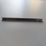
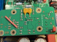
Yes, we are well aware of this problems as it is concerns other chassis as well. What we usually do is add a "L-shaped" bracket between the edge of the rear panel and of the bottom cover which makes the cover less likely to blend. You can find a picture attached. This would just add a couple of EUR to the final price.
If the vertical gaps between the pairs of inputs and outputs, currently ? 5 ? mm were to be say 3 mm more; and the spaces between the four inputs were closer to the spaces between the outputs …
If that then encroached on the surrounding labels/ so the labels then would look not quite right, if it were a hassle to stretch the labels, I would fine with leaving those labels on the right hand size .. off.
That can be easily changed too
Attachments
The original Yarra chassis GB was here.
YARRA Preamplifier Custom Case at Modushop
We can start a new GB2 interest list there.
YARRA Preamplifier Custom Case at Modushop
We can start a new GB2 interest list there.
Ok, GB2 interest list had been started over in the chassis GB thread:
YARRA Preamplifier Custom Case at Modushop
YARRA Preamplifier Custom Case at Modushop
DC coupled
Hello,
I have retrieved these tips from X:
"I think that maybe the best thing to do is have no output caps on the main board and let the daughterboards each handle AC coupling in their own. That way, DC coupled amps like Melbourne and WB18 can run unfettered by any cap induced bass fall-off."
"My all around recommendation is 1000uF audio grade like Silmic, your favorite 2.2uF to 4.7uF film cap like a Wima MKP or even a Mundorf film in oil cap. That should be swell."
On this I understand and it is my intention, to use yarra preamp only and only preamp with Hakuin DB. In PCB Hakuin I would like to use in C113 a good film capacitor and value 2,2uf (despite the little space) and a 1K bleed resistor.
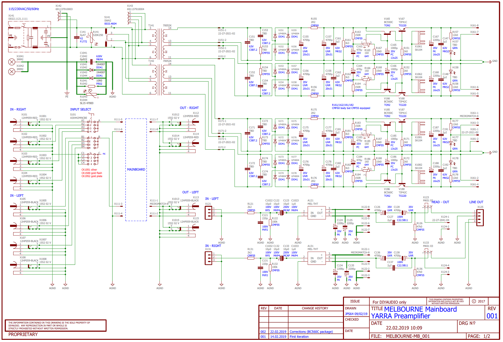
On the main board yarra ring with a bridge C1022 / 122/123/1023 and on the other channel C1032 / 132/133/1033.
I would also replace C126 / 128 and C136 / 138 with 4 Elna Silmic 22uF. Would my thoughts be correct for the DC issue?
I will not have cut in low frequencies?
Can I also delete the 4 Elnas 22uf?
Thanks in advance and greetings
Hello,
I have retrieved these tips from X:
"I think that maybe the best thing to do is have no output caps on the main board and let the daughterboards each handle AC coupling in their own. That way, DC coupled amps like Melbourne and WB18 can run unfettered by any cap induced bass fall-off."
"My all around recommendation is 1000uF audio grade like Silmic, your favorite 2.2uF to 4.7uF film cap like a Wima MKP or even a Mundorf film in oil cap. That should be swell."
On this I understand and it is my intention, to use yarra preamp only and only preamp with Hakuin DB. In PCB Hakuin I would like to use in C113 a good film capacitor and value 2,2uf (despite the little space) and a 1K bleed resistor.
On the main board yarra ring with a bridge C1022 / 122/123/1023 and on the other channel C1032 / 132/133/1033.
I would also replace C126 / 128 and C136 / 138 with 4 Elna Silmic 22uF. Would my thoughts be correct for the DC issue?
I will not have cut in low frequencies?
Can I also delete the 4 Elnas 22uf?
Thanks in advance and greetings
Hi otto,Hi redjr
I’m about to buy the Yarra and want to make sure it ticks every box.
Your implementation - with the addition of Meldano’s Muse/ looks pretty well perfect …
https://www.diyaudio.com/forums/search.php?searchid=24746755
I’ve just checked, and the PCBs and microcontroller are still available
A couple of simple/ dumb questions -
“To attach the VC, I used one of the small unused PCBs included with the Yarra kit” - that was one of the daughterboards? I’d guess - the smallest one?
It’s available in “ available in SE output, or using 2 stereo boards - balanced as well” - for the Yarra, you bought the SE?
Your display looks * very professional
> is optional
A Diyaudio guy (Meldano) also supplied a display? (If not, do you recall where you got it?)
The custom hole in the thick front plate - hopefully/ presumably Modushop could do it? (for extra) so it’s all one purchase. I guess the display comes with mounts, so size the hole for the right match.
Much appreciated
Sorry for the late reply.
I had to go look, but it is the board for the smallest VC - that came with the Yarra kit. I believe I got a last spare from x. I did have to bend some connector pins a bit to get it all to fit, but certainly doable.
Yes. I bought a stereo (SE) version that included 2 boards. The MPU board, and a single volume board(2-Channel).
The display is a simple 7-segment display from Adafruit. You can find it here.
More information above this version can be found in meldano's documentation. I have attached it.
Hope this helps. I have sent you a PM.
Attachments
Hello,
I have retrieved these tips from X:
"I think that maybe the best thing to do is have no output caps on the main board and let the daughterboards each handle AC coupling in their own. That way, DC coupled amps like Melbourne and WB18 can run unfettered by any cap induced bass fall-off."
"My all around recommendation is 1000uF audio grade like Silmic, your favorite 2.2uF to 4.7uF film cap like a Wima MKP or even a Mundorf film in oil cap. That should be swell."
On this I understand and it is my intention, to use yarra preamp only and only preamp with Hakuin DB. In PCB Hakuin I would like to use in C113 a good film capacitor and value 2,2uf (despite the little space) and a 1K bleed resistor.
On the main board yarra ring with a bridge C1022 / 122/123/1023 and on the other channel C1032 / 132/133/1033.
I would also replace C126 / 128 and C136 / 138 with 4 Elna Silmic 22uF. Would my thoughts be correct for the DC issue?
I will not have cut in low frequencies?
Can I also delete the 4 Elnas 22uf?
Thanks in advance and greetings
Hello,
Any advice on this?
I'm trying to figure out the correct capacitor values to slow down the DC component (Hakuin-Yarra) without sticking to smooth low frequencies and if I can eliminate any signal passing capacitor, the better.
(Sorry for my low level of the English language)
Greetings!
Hi Karucho,
When posting specific questions about schematics please post the schematics as I don’t have these memorized in my head
So your question is if your selection of main on-board caps of 4x 22uF enough for proper bass extension? You will be installing all AC coupling caps on the main board, 2.2uF in input and two 22uF in series on the output?
The 2.2uF on input is fine. The two 22uF in series gives 11uF only. If you only plan to use Hakuin then back to back output cap is not needed to be bipolar. Just use one (+ve facing the Hakuin output) and put a jumper in the second.
A single 22uF will limit your bass extension for a headphone load of 250ohms to 30Hz, but probably ok for a preamp driving an amp. Let’s assume your load that you are driving is 10k ohm.
The -3dB cutoff frequency of a 1st order high pass RC filter is 1/(2pi R C). 1/(2pi x 10kohm x 22uF) = 0.3Hz. I usually will go two octaves up to see where it starts not being flat. So I get 1.38Hz for -3dB and this is good down to 5.5Hz. But, if your amp is input lower you may notice some loss of bass. If you used them back to back, then it would be 11Hz.
I would go with at least 47uF output cap, single not back to back.
Hope that helps.
Last edited:
Hi X, I am sorry I did not publish the scheme, you are absolutely right.
Thank you very much for the explanation and I don't know if my hard brain has understood it ...
In the yarra scheme that you have published and speaking only of one channel "in left":
C1022 / 122/123/1023 -------- 2.2uf Capacitor quality
C126 / 127/128 -------- 47uf Elna Silmic
In DB Hakuin's schematic:
C103 / 104 --------- 2,2uf Capacitor quality
C113 / 114 --------- Bypassed
Is my plan correct?
Greetings
Hi Karucho,
My Yarra preamp is strictly for line level use, no headphone usage at all. So all my daughter boards are built with this in mind.
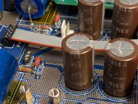
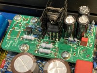
I have my Hakuin boards currently installed. Since the Yarra motherboard already has all the input components and a large area for a nice PP capacitor (at least 4.7uF size), they need not to be duplicated on the Hakuin DB’s. Same for the output caps. Back to back 220uF Silmic II’s with a Wima PP are installed on the main board. Eliminate the 1000uF cap and replace with a jumper on the Hakuin. Keep an eye on your input psu voltage, use the Hakuin CRCRC R121 and R122 to fine tune your working voltage.
Change the bleed resistors R126/R136 to 1K2 or similar on main board.
The Toshiba loaded Hakuin’s sound very good!

My Yarra preamp is strictly for line level use, no headphone usage at all. So all my daughter boards are built with this in mind.
I have my Hakuin boards currently installed. Since the Yarra motherboard already has all the input components and a large area for a nice PP capacitor (at least 4.7uF size), they need not to be duplicated on the Hakuin DB’s. Same for the output caps. Back to back 220uF Silmic II’s with a Wima PP are installed on the main board. Eliminate the 1000uF cap and replace with a jumper on the Hakuin. Keep an eye on your input psu voltage, use the Hakuin CRCRC R121 and R122 to fine tune your working voltage.
Change the bleed resistors R126/R136 to 1K2 or similar on main board.
The Toshiba loaded Hakuin’s sound very good!
Attachments
- Home
- Group Buys
- The YARRA Preamplifier/HPA for Melbourne DB Group Buy