Thanks to a very observant friend who noticed the frequency of ripple, the mystery shrouding the weird synphase connection has finally been revealed
It is perhaps worth warning any adventurous synphasers that in this mode the 4320 works as a parallel half wave rectifier with the obvious increase in ripple. It may be appropriate for this info to also find a spot within the first post of this thread.
The 50Hz ripple can be seen in both simulation and measurements.
In the standard unipolar connection the 4320 applies out of phase control signals to the opposing fets in the bridge, emulating the behaviour of a standard diode bridge. In the synphase connection this changes and the opposing fets get synphase signals at their gates, effectively working in parallel.
Below is the 50Hz ripple waveform from the synphase simulation. In the standard connection this is of course 100Hz.
On the plus side this is an elegant way to achieve half wave rectification without passing dc through the transformer secondary.
Hi analog_sa
So you are saying that these boards produce a half rectified dc?
Is a full wave rectification possible with the 4320?
I am not saying this at all. The standard datasheet connection certainly produces a full rectified output. It is only the centre tapped connection which produces half wave rectified output which is no big deal since factory made centre tapped transformers are incompatible anyway.
The only way possible to obtain a fully rectified bipolar supply is to use a transformer with separate secondaries and separate 4320 boards. In this sense the opening post in this thread is misleading and should be corrected.
The only way possible to obtain a fully rectified bipolar supply is to use a transformer with separate secondaries and separate 4320 boards. In this sense the opening post in this thread is misleading and should be corrected.
Thanks for the update Tibi. I'll leave the GB open for now and we can revisit towards the end of the year.
I assume all GB subscribers will have notifications set so will be aware, via these posts, of the delay in the Mosfets becoming available and the knock-on delay to progressing the GB. Hopefully everyone will appreciate that this is not controllable.
I assume all GB subscribers will have notifications set so will be aware, via these posts, of the delay in the Mosfets becoming available and the knock-on delay to progressing the GB. Hopefully everyone will appreciate that this is not controllable.
Jan,So yes, increasing the capacity smooths the voltage but worsens the other mentioned factors. There's no hard law but 3 x 68000uF is way overkill. 1/5th would avoid a lot of problems.
You should download PSUDII and play with it, very instructive.
Jan
How would one simulate a circuit employing the 4320 in PSUD2?
Thanks,
Ron
Hi,
I want to revise my quantity from 2 to 4.
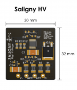
Also, can it be confirmed what is the max voltage? It was originally mentioned as high as 200V, but on the Twitter I saw 150V.
I assume the twitter spec is most recent and most correct--am I right?
Thanks,
Ron
nautibuoy - 2 Saligny HV
Jazid - 2 Saligny HV
ste - 1 Saligny HV
Luca72c - 3 Saligny HV
Rinman77 - 4 Saligny HV
merlin el mago - 1 Saligny HV
nightsky -2 Saligny HV
s610adam - 4 Saligny HV
Total = 19
I want to revise my quantity from 2 to 4.
Also, can it be confirmed what is the max voltage? It was originally mentioned as high as 200V, but on the Twitter I saw 150V.
I assume the twitter spec is most recent and most correct--am I right?
Thanks,
Ron
nautibuoy - 2 Saligny HV
Jazid - 2 Saligny HV
ste - 1 Saligny HV
Luca72c - 3 Saligny HV
Rinman77 - 4 Saligny HV
merlin el mago - 1 Saligny HV
nightsky -2 Saligny HV
s610adam - 4 Saligny HV
Total = 19
...or perhaps 150 AC --> ~200 DC ?
That would work great for me as I have +/- 94 VDC rails
See post #330
https://www.diyaudio.com/forums/group-buys/333844-ideal-bridge-rectifier-gb-33.html#post5992991
Clear enough, and good news for me.
Thanks,
Ron
The bridge presented on twitter is with a lower voltage MOSFET.
The MOSFET's I have ordered and postponed by mouser, are rated 200Vdc. The bridge will handle even more than 200Vdc. I have ordered an variable autotransformer to perform some tests and see exactly at which voltage the bridge get destructed, but first I need mouser to deliver the order.
Regards,
Tibi
The bridge presented on twitter is with a lower voltage MOSFET.
The MOSFET's I have ordered and postponed by mouser, are rated 200Vdc. The bridge will handle even more than 200Vdc. I have ordered an variable autotransformer to perform some tests and see exactly at which voltage the bridge get destructed, but first I need mouser to deliver the order.
Regards,
Tibi
Better yet!
")
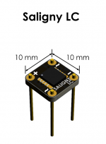
Currently minimum Saligny voltage is aprox. 6,3Vac. After rectification you get 9Vdc and this is perfect in case you need a regulated 5V voltage.
To answer your question, yes we have developed a Saligny AUTO able to work from 0,55Vac up to 42Vac at 300A. This target Automobile market.
Regards,
Tibi
To answer your question, yes we have developed a Saligny AUTO able to work from 0,55Vac up to 42Vac at 300A. This target Automobile market.
Regards,
Tibi
- Home
- Group Buys
- Ideal bridge rectifier GB