Sounds good in my phono, but I'm not sure yet whether it's smoother than what I was using, or if it's a got a little less timbre or.... We'll see! It's certainly a well working device.
But I suggest swapping one of the AC inputs and V- just because then you don't have to untwist the cables so much. Locating them on opposite ends of the board wouldn't be a problem either, or whatever makes the most sense.
But I suggest swapping one of the AC inputs and V- just because then you don't have to untwist the cables so much. Locating them on opposite ends of the board wouldn't be a problem either, or whatever makes the most sense.
I also need to put more smoothing capacitance in. I just removed my DCS1, I think I’ll just remove the diodes on it and adapt it. Maybe then the pin out will be more useful. Right now it’s just two wire sets in a heatshrink sock.
Pin out converts well to a 4x TO220.
While this may have some really good attributes for class A, when the big ones come out, it works nicely for small signal stuff.
I installed a Saligny in place of a common SMD full wave bridge rectifier in a LT3042 based supply with a series pass transitor as described in the data sheet for the LT3042, see:
https://www.analog.com/media/en/technical-documentation/data-sheets/3042fb.pdf
Page 27, for example. The supply is used to power the DAC board of an Allo Katana DAC including the ESS9038Q2M and its associated NDK oscillators.
The difference is nothing short of shocking.
Everything described herein above. More detail, more character, better delineation, more authority, etc. - and without being more difficult to listen to. In fact, the opposite. I'm able to listen louder without discomfort as well - always a good sign.
The same was heard by at least two others who are very familiar with my system, one of which was able to identify the difference after a month or so hiatus from the system.
I don't know that I could now go without the Saligny...it is that much better....now, to use it elsewhere...
Tibi,
Any further information on this? Or, updates??
Any further information on this? Or, updates??
Hi Jan,
For tube fans I'll have discrete ideal diodes that will handle up to 450V at 6A.
Hope the end of soft tube rectification is near.
Regards,
Tibi

Thank you for delivery confirmation !
I used straight pins and bended at 90 degree.
2PH1-40-UA ADAM TECH - Pin header | TME - Electronic components
You may use one that is already angled at 90 degree, or solder some wires.
2PH1R-40-UA ADAM TECH - Pin header | TME - Electronic components
Regards,
Tibi
I used straight pins and bended at 90 degree.
2PH1-40-UA ADAM TECH - Pin header | TME - Electronic components
You may use one that is already angled at 90 degree, or solder some wires.
2PH1R-40-UA ADAM TECH - Pin header | TME - Electronic components
Regards,
Tibi
Tibi,
Thanks for responding.
I think there will be enough interest in a 450V at 6A ideal diode, but - I also think you have to prove or at least provide some empirical evidence or an accounting that it is sonically beneficial first. Once that is done, it should be much easier to reach 100 units.
Frankly, right now any benefits at higher voltages in tube power supplies is based solely on conjecture or extrapolation from the benefits found at lower voltages in solid state power supplies. It may not follow. Not that I have any reason to believe it won't; but, as far as I know, it hasn't been confirmed it yet.
Additionally, I don't think you'll generate as much of a following here as what you might on say, a "tube" forum.
Further, I think the "SalignyHV @ 200V" is a bit of a misnomer, at least in terms of the voltages commonly used in tube circuits. While 200V might be considered HV in solid state terms, it frankly is pretty much useless in tube terms. Maybe a bias supply, but that's about it. I think Jan might have indicated this earlier...
At any rate, if you're willing to share what you're thinking or have built for a 450V at 6A ideal diode, i'd be willing to try them in various tube power supplies and give you some feedback. Further, if feasible, i'd be willing to build one at my own expense and try it.
Short of that, you might be "dead in water" as they say.
Hope that helps...
I have such project on my workbench, but are there enough people interested in a 450V at 6A ideal diode ?
Can we reach at least 100 units ?
On other hand, SalignyHV @ 200V is almost ready.
Regards,
Tibi
Last edited:
Tibi,
You're welcome, looking forward to it -
The transistor part looks the easier of the two. The substitution or replacement for the LT4320 or "controller" looks more difficult.
In addition to a full wave bride configuration, I'd also allow for the situation where a center tapped transformer is used as that is pretty common...
Thank you for your comments, jrocker.
I'll share more info when I have first working prototype.
Regards,
Tibi
...
At any rate, if you're willing to share what you're thinking or have built for a 450V at 6A ideal diode, i'd be willing to try them in various tube power supplies and give you some feedback. Further, if feasible, i'd be willing to build one at my own expense and try it.
...
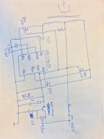
Here is a quick draw on how such solution may be implemented using UCC24624.
The juicy part is mosfet selection.
Regards,
Tibi
Attachments
Tibi,
Thanks again.
So, for those following along, basically, the two BSS127 MOSFETs provide for the 200 volt limitation of the UCC24624 between its VD1 and VD2 pins, and its ground (Vss in the drawing). Similarly, the KSC5502 reduces the voltage at the VDD pin of the UCC24624. These together provide for operation of the UCC24624 in supplying more than 200 volts, or 300-450 volts as also indicated on the schematic.
Now, the selection of the two rectifier devices, indicated as ???, on the schematic. Have you thought about the GS66502B from GaN Systems as a candidate? I know of one instance of two of them being used with the gate tied to the source in CT arrangement (80+80) for a B+ of 120VDC. The Cree C3M0280090D?
jroker,
You got it right. BSS127 depletion mosfet's are there to limit Vd seen by UCC24624 at very low level. Entire high voltage job is took by BSS127.
KSC5502 is a simple regulator to 12V. The single issue here is with 47K resistor that will dissipate some power. Depending on UCC operation that resistor may be increased to 100K. Any other high voltage regulator may be used.
Both GS66502B and C3M0280090D are very good canditates. Rdson is over 0,2ohm but power dissipated at 10A will be far less than any tube rectifier.
Regards,
Tibi
Hi Tibi. Just an update that my two modules arrived safely yesterday. Thank you.
Let us know your subjective opinion?
- Home
- Group Buys
- Ideal bridge rectifier GB