You can change the DSP functions using SigmaStudio, a free download which you install on a PC.Finally I'm also listening to 2x 3255 + dsp board; the sound is great!
Can anyone share the default settings of the dsp board?
X-over frequency, maybe any gain settings? Is it possible to modify the bass control so it cuts out completely? (now it doesn't)
Has any put a on/off switch to the Bluetooth module? Is that done by bending out the power-pin and adding a switch or is there a nicer solution?
SigmaStudio | Analog Devices
Use the USB interface board (supplied) to connect the PC to your DSP board. You will probably want to download a copy of the current source files found at the bottom of this page, and drivers for the USB interface board.
ADAU1701-2In4Out | 3e Audio
It's probably easier to modify this than to start from scratch. This is the program currently loaded onto your DSP board, so if you mess up you can just reinstall it to get back to where you started.
I realise this probably isn't the easy answer you were hoping for, but it is the answer. If you get this set up properly it should not be too hard to change the xover frequency or remove it completely.
Last edited:
I am too struggling to come to terms with the dsp board.
I have 3e 3255 2ch and 3e 3251 3ch....both from Ebay prior this group buy . Lovely products. But some support for the dsp would be good. I guess we are supposed to go to the free USB forum.
I have tried to get drivers for USB and Win10 64 working but to no avail so far
I have 3e 3255 2ch and 3e 3251 3ch....both from Ebay prior this group buy . Lovely products. But some support for the dsp would be good. I guess we are supposed to go to the free USB forum.
I have tried to get drivers for USB and Win10 64 working but to no avail so far
I am too struggling to come to terms with the dsp board.
I have 3e 3255 2ch and 3e 3251 3ch....both from Ebay prior this group buy . Lovely products. But some support for the dsp would be good. I guess we are supposed to go to the free USB forum.
I have tried to get drivers for USB and Win10 64 working but to no avail so far
Download the driver and sigma code from 3e-audio website, load sigma studio, load the code file, go into into second schematic tab, crossover then.....if you are using a proper stereo speaker with built in crossover and protection just remove the low pass filter compile download and then write to DP’s memory you should be laughing afterwards
The only issue I’m having is with Bluetooth range it’s dismal at best I tried a couple of different antennas with IPEX end but still no joy anyone else is having the same problem how can I boost the Bluetooth reception?
when you use that extenal antenna,you need swap(need solder skill) the cap default used for on board antenna.Download the driver and sigma code from 3e-audio website, load sigma studio, load the code file, go into into second schematic tab, crossover then.....if you are using a proper stereo speaker with built in crossover and protection just remove the low pass filter compile download and then write to DP’s memory you should be laughing afterwards
The only issue I’m having is with Bluetooth range it’s dismal at best I tried a couple of different antennas with IPEX end but still no joy anyone else is having the same problem how can I boost the Bluetooth reception?

in Win10,you need disable something like safety singurated setting,please see install document detail.I am too struggling to come to terms with the dsp board.
I have 3e 3255 2ch and 3e 3251 3ch....both from Ebay prior this group buy . Lovely products. But some support for the dsp would be good. I guess we are supposed to go to the free USB forum.
I have tried to get drivers for USB and Win10 64 working but to no avail so far
thanks!
I found that if I turn the amp on, then right away turn it off and back on, the whine is gone. What would cause this? @3eaudio?I assembled my amp and power supply and I'm getting a whine from the large transformer in the power supply as well as left channel of the amp (the channel closer to the transformer). Any suggestions on how to resolve this?
Thanks,
Nate
 Thanks
when you use that extenal antenna,you need swap(need solder skill) the cap default used for on board antenna.
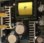
View attachment 747866
Well you sent me a different bluetooth board compared to the one in the picture despite my order which clearly said 3008.
One I received was the 6415 which has built in IPEX for external antenna.
Are you trying to say that the IPEX is not connected?
Well you sent me a different bluetooth board compared to the one in the picture despite my order which clearly said 3008.
One I received was the 6415 which has built in IPEX for external antenna.
Are you trying to say that the IPEX is not connected?
I found that if I turn the amp on, then right away turn it off and back on, the whine is gone. What would cause this? @3eaudio?
Thanks,
Nate
it may be something like in standby mode cause this,
you can try to glued the components like this
Attachments
I’ve been testing a generic (“Nobsound”) TI reference design of the TPA3255 and noticed that it is very sensitive to input pops and clicks from source material. It will go into fault mode and require power cycle to reset. That’s a problem for me - is it simply the reference design or inherent in the TPA3255 chip itself? I realize it is there to protect speakers - but there has to be a better way to reset (maybe automatically?).
I have a TI 3255 EVM board (the definitive reference design) and have never once had this problem in over a year of use. I have implemented an external reset switch for switch on and off pops, or you can use power on/off relays which delay the unmute until the power has been up for a while. The 3255 chip has a reset pin which mutes the amp when the pin is grounded, in my case through a switch and pulldown resistor to circuit ground. I have never known a clean signal to trip an error condition except clipping protection when I drove it very hard, which resets itself instantaneously. The first thing I would suggest is work out which specific error condition you are getting.
If Nobsound haven't implemented this mute/reset feature they've made a mistake in my view, particularly since it is very simple to implement and requires two cheap components. At present I think there are two iterations of the 3255 worth having as a power amp, both in board form. The 3e 3255 stereo board sold in this thread, and the design it is based on, which exposes all the functions of the chip, the TI 3255 EVM board.
Allo are supposedly developing a boxed 325x amp which is likely to be decent going by their past record. The one low cost implementation I've heard about was short on features and decoupling caps were inadequate in my opinion.
Maybe consider posting in one of the generic 325x threads if you want specific help for these problems, this group buy doesn't involve your hardware. The 3255 documentation from TI is also very comprehensive.
Last edited:
Thanks - posted in general 3255 thread and will take a look at documentation. Good to know real TI reference design doesn’t have this issue.
Has anyone looked at the residual switch noise coming out of this amp? My scope shows a 270mV sine-like 450kHz wave. My ears can hear a hiss when pressed to the speaker cone. Not silent definitely. How is TI or e3 design with regards to residual leakage or hiss?
Has anyone looked at the residual switch noise coming out of this amp? My scope shows a 270mV sine-like 450kHz wave. My ears can hear a hiss when pressed to the speaker cone. Not silent definitely. How is TI or e3 design with regards to residual leakage or hiss?
Can you explain in more detail why you think this is happening? Are you suggesting I glue the components down myself? I'm not sure what glue to even use. Could this be a manufacturing defect?it may be something like in standby mode cause this,
you can try to glued the components like this
Thanks,
Nate
sorry for mixed this,
the 64215 one is different with 3008
but you still can solder an external antenna for better receiving sensitivity
How? Please give me details
In the manual for the ADAU1701 (EDSP-1701-24-A) you write "Single-end input voltage Full-Scale - 1.1- 1.2 Vrms" and as note "Full-scale input voltage can meet 2Vrms by changing input resistor: 8.2kohm-> 18kohm "
Is that correct ? if so, which resistor needs to be replaced, where exactly is it on the board? can you please take a picture?
Is that correct ? if so, which resistor needs to be replaced, where exactly is it on the board? can you please take a picture?
for DIY stuff,we did not implement that but only for OEM customer.Can you explain in more detail why you think this is happening? Are you suggesting I glue the components down myself? I'm not sure what glue to even use. Could this be a manufacturing defect?
Thanks,
Nate
then you need try yourself,sorry for this.
by change R5,R6 to get different input level.In the manual for the ADAU1701 (EDSP-1701-24-A) you write "Single-end input voltage Full-Scale - 1.1- 1.2 Vrms" and as note "Full-scale input voltage can meet 2Vrms by changing input resistor: 8.2kohm-> 18kohm "
Is that correct ? if so, which resistor needs to be replaced, where exactly is it on the board? can you please take a picture?

- Home
- Group Buys
- Group buy: TPA3251_TPA3255 Amplifier board and ADAU1701 DSP Pre-Amp board