Count me in for two if price ok...
Supersurfer .....1 at least
aguaazul ...........2 (maybe 4)
al2813..............1
ernesternest ....1
ppap64 ............2
asanden ......... 2
Vunce ............. 1
androa76 ........ 1
savvas ............ 2
analog_sa.........2
darrr....... 1
also showed interest
advr
bisesik
obh ................ 2
Supersurfer .....1 at least
aguaazul ...........2 (maybe 4)
al2813..............1
ernesternest ....1
ppap64 ............2
asanden ......... 2
Vunce ............. 1
androa76 ........ 1
savvas ............ 2
analog_sa.........2
darrr....... 1
also showed interest
advr
bisesik
obh ................ 2
Supersurfer .....1 at least
aguaazul ...........2 (maybe 4)
al2813..............1
ernesternest ....1
ppap64 ............2
asanden ......... 2
Vunce ............. 1
androa76 ........ 1
savvas ............ 2
analog_sa.........2
darrr....... 1
Mayday....... 1 (maybe 2)
also showed interest
advr
bisesik
aguaazul ...........2 (maybe 4)
al2813..............1
ernesternest ....1
ppap64 ............2
asanden ......... 2
Vunce ............. 1
androa76 ........ 1
savvas ............ 2
analog_sa.........2
darrr....... 1
Mayday....... 1 (maybe 2)
also showed interest
advr
bisesik
If not crazy price, i would also take one.
Supersurfer .....1 at least
aguaazul ...........2 (maybe 4)
al2813..............1
ernesternest ....1
ppap64 ............2
asanden ......... 2
Vunce ............. 1
androa76 ........ 1
savvas ............ 2
analog_sa.........2
darrr....... 1
also showed interest
advr
bisesik
obh ................ 2
LinuxGeek ........... 1
Supersurfer .....1 at least
aguaazul ...........2 (maybe 4)
al2813..............1
ernesternest ....1
ppap64 ............2
asanden ......... 2
Vunce ............. 1
androa76 ........ 1
savvas ............ 2
analog_sa.........2
darrr....... 1
Mayday.... 1 (maybe 2)
also showed interest
advr
bisesik
obh ................ 2
LinuxGeek ........... 1
Supersurfer .....1 at least
aguaazul ...........2 (maybe 4)
al2813..............1
ernesternest ....1
ppap64 ............2
asanden ......... 2
Vunce ............. 1
androa76 ........ 1
savvas ............ 2
analog_sa.........2
darrr....... 1
Mayday.... 1 (maybe 2)
also showed interest
advr
bisesik
obh ................ 2
LinuxGeek ........... 1
Malvin ......1
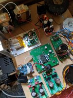
Off topic I know ") but I just swapped Pedjas AD844 output stage for Thorsten's ECC88 anode follower. My D3 is plonked in the middle of a total lash up just to feel the right direction to go, but I did the tube power supply with some care as its critical. I'm quite staggered with the transformation. If you haven't tried tubes with the D3 I'd strongly encourage it.
but I just swapped Pedjas AD844 output stage for Thorsten's ECC88 anode follower. My D3 is plonked in the middle of a total lash up just to feel the right direction to go, but I did the tube power supply with some care as its critical. I'm quite staggered with the transformation. If you haven't tried tubes with the D3 I'd strongly encourage it.
but I just swapped Pedjas AD844 output stage for Thorsten's ECC88 anode follower. My D3 is plonked in the middle of a total lash up just to feel the right direction to go, but I did the tube power supply with some care as its critical. I'm quite staggered with the transformation. If you haven't tried tubes with the D3 I'd strongly encourage it.Attachments
I guess it's alright to talk about output stages in D3 thread, in some extend, not hijacking it
That's an early S1 you've got there. Other than Lundahls what other care you are referring ?
What you like more in the tube output stage vs AD844 ? I guess that AD844 was doing the buffer duties also or was it Jfet based ?
That's an early S1 you've got there. Other than Lundahls what other care you are referring ?
What you like more in the tube output stage vs AD844 ? I guess that AD844 was doing the buffer duties also or was it Jfet based ?
I guess it's alright to talk about output stages in D3 thread, in some extend, not hijacking it
That's an early S1 you've got there. Other than Lundahls what other care you are referring ?
What you like more in the tube output stage vs AD844 ? I guess that AD844 was doing the buffer duties also or was it Jfet based ?
My S1 is the only remaining part I have from an Arcam 70.2 I bought thirty years ago!
The HT is CRC filtered with some Mundorf Mlytic AG+
Pedja's early AD844 AYA circuit is not in the public domain, so I can't post it. It's similar in principle to the later OP861 circuit.
OPA861 zero-feedback output stage of AYA II - Audial
Obviously Pedja's circuit uses a LOT less resources and does sound better than any conventional opamp i/v I've tried but the ECC88 has so much more air, spaces between instruments open up, tiny details emerge and the soundstage grows deeper. Complex harmonic structures are more resolved. The only downside is the bass has put on a few inches around the waistline
Early days though, much more tweaking to be done!Thanks for the info Simon,
I assume that you use resistor for I/V conversion.
IIRC Pedja has actually given his earlier work with AD844 with Jfet buffer (he used 2sk170) eventually he dismissed this implementation in favor of AD844 doing double duty as I/V and buffer.
D3 it's great base if you are in a mood for playing around with the rest of the circuit for TDA1541. After finishing my AYA I'd give it a try along with tube output stage.
Hi,
I have received the TDA1541A S1 dac chips. Please see my post in the swap meet forum:
New Old Stock! TDA1541A S1 single crown for sale
I have received the TDA1541A S1 dac chips. Please see my post in the swap meet forum:
New Old Stock! TDA1541A S1 single crown for sale
So iancanada is so far past Fifo V1 and is all into Pi stuff is the old V1 still available anywhere? Do you know if Twisted Pear's Cronus re-clocker is a viable option? I know Andreas has a re-clock project in the works but I have not seen that it is ready. Anyone who can help. I am planning 2 D3 in simultaneous mode. Any ideas would be appreciated.
best regards,
Steve
best regards,
Steve
Finally taking the plung!
Greg, Ryan and D3 community,
After enjoying the original for years, I am finally building D3. I reread the D2 and D3 threads and it occurred to me that it would be a shame to not experience the design refinements in D3.
I saw many references to challenges soldering the four layer pcb without cooking the IC's. Thanks Greg for the build guide.
So I finally bought a budget Chinese soldering station with lots of tips. I already had a good air station and a toaster oven which worked well for reflow on past projects.
I bought the recommended low temp solder paste and set about to practice using a D2 pcb. Wow!. It is different soldering a four layer.
My question to those who have succeeded is what temp to use on the soldering iron? My cheap station may not have an accurate read on temp. I tried 300F and it would not melt the paste. At 350F it barely gets it melted after what seems like far too long. At 450F the paste will flow fairly reasonably.
I am just wondering what you found to be best practice on soldering the IC's getting the solder to flow but not fry the little guys. I took the recommendations and bought spares for all the IC's and the MELF resistors.
It strikes me I could start with paste to do the power supplies and reflow that in the oven following the flow profile for the paste. I think it goes briefly to 325F. Or I could preheat the PCB to 250F and come at it with paste and then an iron at say 400F for a brief touch. Or just use paste and hit it with 450F iron briefly and pray.
Sorry for the basic question, but I suspect many have been through this and I would appreciate your perspective.
Anyone else working on their D3? For those of you who have boards but haven’t started, let’s get those done!
Cheers,
Greg
Greg, Ryan and D3 community,
After enjoying the original for years, I am finally building D3. I reread the D2 and D3 threads and it occurred to me that it would be a shame to not experience the design refinements in D3.
I saw many references to challenges soldering the four layer pcb without cooking the IC's. Thanks Greg for the build guide.
So I finally bought a budget Chinese soldering station with lots of tips. I already had a good air station and a toaster oven which worked well for reflow on past projects.
I bought the recommended low temp solder paste and set about to practice using a D2 pcb. Wow!. It is different soldering a four layer.
My question to those who have succeeded is what temp to use on the soldering iron? My cheap station may not have an accurate read on temp. I tried 300F and it would not melt the paste. At 350F it barely gets it melted after what seems like far too long. At 450F the paste will flow fairly reasonably.
I am just wondering what you found to be best practice on soldering the IC's getting the solder to flow but not fry the little guys. I took the recommendations and bought spares for all the IC's and the MELF resistors.
It strikes me I could start with paste to do the power supplies and reflow that in the oven following the flow profile for the paste. I think it goes briefly to 325F. Or I could preheat the PCB to 250F and come at it with paste and then an iron at say 400F for a brief touch. Or just use paste and hit it with 450F iron briefly and pray.
Sorry for the basic question, but I suspect many have been through this and I would appreciate your perspective.
I built my D3 with a magnifier, soldering iron and thin solder wire. A little solder on one pad, place the component with tweezers tacking the component in place on the pre soldered pad. Then solder the rest of the joints in place. I used some hot air to pre-heat local areas where there was a larger area of copper involved. It worked first time.
Solder paste is all very well if you have a silk screen to accurately apply it, a pick and place machine, and can flow the whole thing in an oven with the correct temp profile...in one go. I find it way too much hassle for hand built boards.
Solder paste is all very well if you have a silk screen to accurately apply it, a pick and place machine, and can flow the whole thing in an oven with the correct temp profile...in one go. I find it way too much hassle for hand built boards.
Last edited:
I don't use anything fancy solder wise, sn/pb should be fine, the key is not to swamp the joints with too much. Here's the process I follow.
How to Solder Surface Mount parts (it's easy!) - YouTube
How to Solder Surface Mount parts (it's easy!) - YouTube
I defer to Ryan. FWIW, I believe I've seen this asked a few times as I reread the thread. I believe the answer is Ryan designed & tested at 26V. He recommends from that up to max 28. He says that below 25.5V it might not perform as well as he tested.
I plan to use my existing supply that runs around 25V.
I plan to use my existing supply that runs around 25V.
Last edited:
Hi,
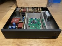
after a very long time on a MDF board my D3 will receive a case. I bought a Linn Intersekt case for very little money and now mod it to my needs.
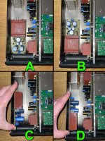
My question is : Which way to mount the PSUs would you prefer and why ? Is there a difference if the transformers are side by side, facing away from each other or even one on the floor one on the wall ? Which would make sense ? Here are my possibilities.
after a very long time on a MDF board my D3 will receive a case. I bought a Linn Intersekt case for very little money and now mod it to my needs.
My question is : Which way to mount the PSUs would you prefer and why ? Is there a difference if the transformers are side by side, facing away from each other or even one on the floor one on the wall ? Which would make sense ? Here are my possibilities.
Attachments
- Home
- Group Buys
- DIY TDA1541A PCB "D3"