Hi androa76,Understand. Do you have any recommendation for silvered ufl cables for connection data lines? Thank you.
I suppose you mean tinned at one end, with the other end terminated with a ufl plug?
Buying two long ufl cables and cutting them in half you could make your own. I have not tried this but should work fine.
Tube I/V?
Soooo late to this party but I'll be building up my D3 soon.
I'm drawn to Thortstens ECC88 I/V for my build Thorsten's tube Stage for TDA1541A but I know nothing of the subtleties of tube circuits.
I'd like to try choke loading the anode as he suggests. I guess the standing current is the important thing to aim for here and the higher the inductance the better? Would a Llundhal L1667 fit the bill? Its 270H and 15mA.
Grateful for any advice. Thanks!
Probably a very stupid question but I can't figure it out.
I see D3 setups with Ian's Fifopi directly to the D3 board and setups with the I2S to simultaneous converter board between the Fifopi and D3 board.
What is the benefit or downside of the setups?
Thanks!
Hi 3kes,
Simultaneous mode in my experience is a much more enjoyable listening experience with the TDA1541A. The sterreo imaging is much more refined and accurate, I also noticed an improvement in the accuracy of the bass.
JLsounds Question
I finally had some time to finish my D3 build, look forward to it. But I run into a no sound issue... I suspect it is on the V1 i2s sim board.
My setup is:
RPI4 + Moode Audio (USB setting) (files play ok)
>>
JLSounds V3; USB>I2S internal clock (internal clock, TDA1541A in I2S mode in 32-bit frame; jumpers on J2, J4 A2, B1, B3 closed) 32 bit means stereo I guess!
Dual external power supply setup
>>
Ryan’s V1 board (I2S > Sim)
>>
Ryan’s D3 board (in J2 simultaneous setting)
>> I/V 50R resistor for the moment
No shorts and such on the UF/L lines.
The D3 has correct power and I can get 0mV on the AOL / AOR once the RPI starts playing a song.
For those familiar with the jlsounds; Is the jlsounds jumper setting correct?, the 32 bit refers to 2x16 stereo channels I guess...
Next step would be troubleshooting the V1 board
Regards, Albert
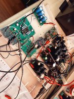
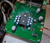
At the moment I have very little time because of 3 month old child, so i have to optimize my time. I am very sorry if this was already explained, i found some info but i am not sure if i explained it right to myselfe. I soldered my boards, connected them to 2 lifepo power supply, so 25,2V and 8,4V followed by tps7a4700 set to 5v. I measured voltages in expected region, just dc offset can not be set to 0V and i can"t measure any output signal with 50r i/v resistor. Here is my work. For the test i use piece of wood, later if sound will be promissing it wil be mounted into alu enclosure. Maybe some mistakes are vissible? I know, i should"t use S1 for testing but, i get A dac in one week and can"t wait another week ") .
.
.Attachments
Last edited:
Follow up on previous post.
Jlsounds needed the standard I2S setup (only B1 and B3), I2S SIM V1, D3 all ok
Very good sound on this test setup
Hear some cracks on some 16 bits sample rates, but ie 176k/16 plays fine
Glad you got it all working. Are the cracks over 176k?
At the moment I have very little time because of 3 month old child, so i have to optimize my time. I am very sorry if this was already explained, i found some info but i am not sure if i explained it right to myselfe. I soldered my boards, connected them to 2 lifepo power supply, so 25,2V and 8,4V followed by tps7a4700 set to 5v. I measured voltages in expected region, just dc offset can not be set to 0V and i can"t measure any output signal with 50r i/v resistor. Here is my work. For the test i use piece of wood, later if sound will be promissing it wil be mounted into alu enclosure. Maybe some mistakes are vissible? I know, i should"t use S1 for testing but, i get A dac in one week and can"t wait another week
Is the 25.2V battery supply floating? its not referenced to ground?
You may also need music playing to get 0V on the outputs.
Last edited:
I had some cracks on lower sample rates, but not anymore...
, believe I loosened the 5V ground pin from the pcb when installing/de-installing the D3 5V connectors, after re-soldering every sample rate 44 kHz (min) ... 196kHz (max) is fine/better.
Next experiments on the I/V stage...
Removed the 1:25 mu core trafo, and put in 100R I/V resistors, connected to a Pass DCB1 and Salas DCG3 so I can A/B the DAC with my DAM1021, difficult to compare for the gain mismatch.
Believe there is still experimenting to do; dual mono? differential? both? tube stage?
Thanks Ryan for the offerings!
Glad you got it all working. Are the cracks over 176k?
Very good work!
First let it break in then, yes, try different output stages.
I use the Abbas hybrid I/V class-a solid stage feeding a tube (5687) buffer.
I have two tube output staged dacs that've I've built. I will never go back to SS only in an output stage.
Yes, the tube is adding distortion but if its the right type (2nd order, positive or negative phase) followed by a lesser amount of the 3rd order it gives me something that a super clean SS I/V cannot: a diffuse soundstage that sounds real. Instruments have town and body that sounds much more real and relaxed.
The second dac is a Sabre dac with a ground grid amplifier (12AU7) being driven by a class-a SS I/V. It is also amazing sounding. I can switch between SS and tube output on this dac and the tube (when level matched) is significantly more enjoyable.
I use Salas high-voltage shunt regs for the B+ supplies for the tube in each dac, therefore, there is no audible noise coming from the output stages of these tube dacs.
This is all of course my opinion.
Up and Running
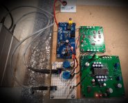
I got my D3 up and running today, it's a long story but I got massively sidetracked before returning to the TDA1541A fold.
I have Pedja Rogic's original AYA which I've been running without the digital receiver section and plumbing in I2S from a JL Sounds USB board. I've hacked the D3 with a super simple power supply onto Pedja's AD844 output stage just to see what kind of flavour I get. Even without it burning in, there is more of the good stuff: resolution, soundstage depth, bass definition and less of the bad stuff: grain and grit.
Thanks Ryan et all, time to get busy implementing!
I got my D3 up and running today, it's a long story but I got massively sidetracked before returning to the TDA1541A fold
. I have Pedja Rogic's original AYA which I've been running without the digital receiver section and plumbing in I2S from a JL Sounds USB board. I've hacked the D3 with a super simple power supply onto Pedja's AD844 output stage just to see what kind of flavour I get. Even without it burning in, there is more of the good stuff: resolution, soundstage depth, bass definition and less of the bad stuff: grain and grit.
Thanks Ryan et all, time to get busy implementing!
Attachments
I got my D3 up and running today, it's a long story but I got massively sidetracked before returning to the TDA1541A fold
I have Pedja Rogic's original AYA which I've been running without the digital receiver section and plumbing in I2S from a JL Sounds USB board. I've hacked the D3 with a super simple power supply onto Pedja's AD844 output stage just to see what kind of flavour I get. Even without it burning in, there is more of the good stuff: resolution, soundstage depth, bass definition and less of the bad stuff: grain and grit.
Thanks Ryan et all, time to get busy implementing!
Hi simon dart,
Good to here you have it all working!
Out of curiosity - What part of the D3 PSU did you take power from to power AD844?
Not sure of the specifics of your output stage but you may want to try the on board +2mA current injection - compared with other solutions it gives less glare and graininess giving a smoother more relaxed sound. Its a subtle change so it will depend on the rest of your system to how well you will hear it.
Hi Ryan, sorry I didn't make it clear. I didn't take any power from the D3 to the output stage, that has it's own discrete shunt regulated supply and jfet +2mA current injection. That side of the AYA is untouched. The schematic is not in the public domain but I believe it's similar in concept to the OP861 that Pedja used for the AYAII.
OPA861 zero-feedback output stage of AYA II - Audial
It's sounding really good. I don't have a pre-amp and my power amp is a little insensitive so I need some gain which is easy to do with this topology. I'd like to try tubes next. So many output stages, so little time
OPA861 zero-feedback output stage of AYA II - Audial
It's sounding really good. I don't have a pre-amp and my power amp is a little insensitive so I need some gain which is easy to do with this topology. I'd like to try tubes next. So many output stages, so little time
Last edited:
Hi Ryan, sorry I didn't make it clear. I didn't take any power from the D3 to the output stage, that has it's own discrete shunt regulated supply and jfet +2mA current injection. That side of the AYA is untouched. The schematic is not in the public domain but I believe it's similar in concept to the OP861 that Pedja used for the AYAII.
OPA861 zero-feedback output stage of AYA II - Audial
It's sounding really good. I don't have a pre-amp and my power amp is a little insensitive so I need some gain which is easy to do with this topology. I'd like to try tubes next. So many output stages, so little time
Ok, gottcha.
I've used k170 jfet for +2ma ccs and preferred the sound from a resistor to deliver the 2ma even though it is not a true ccs - not really sure why it sounds better but I noticed less graininess.
Have fun trying different OP stages! So many flavours to taste!
Hi Ryan,
What sort of power supply can we use for a 5V ? A well filtered LM317 Based is sufficient or anything better is recommended ?
For 26V i am planning to use Salas Ultra BiB.
Thanks
Harsha
Hi Harsha,
Yes those suggestions many do just fine.
Have a read of the D3 build guide if you haven't done so already - many of the commonly asked question are answered in there.
D3 Build guide
- Home
- Group Buys
- DIY TDA1541A PCB "D3"