Hi Greg,
Those voltages are good, once you put all the caps in place the voltages will come up to spec.
Ryan,
Okay, so everything was fine (voltage wise at 15, 26, and 28), populated everything and I am exactly 5 volts short on CC1 output, which of course puts pin 15 at ~-10 volts and pin 26 at ~-millivolts.
I already swapped CC1 out, but that did not solve anything.
I'm also getting ~26v out of C10.
Any ideas....
Thanks,
Greg
Hi Greg,
Sorry to hear that you are experiencing issues with your board. If Ryan hasn't had an opportunity to help you yet, I can give you some information that hopefully is of some use.
CC1 in the circuit is a constant current source, and is unlikely to be the cause of the low voltage.
The negative voltage supplies is comprised of -5V and -10V regulated supplies, providing -5V separately and combining to supply -15V. Since you are getting 0V at the -5V and -10V at the -15V, that points to a problem in the -5V supply. The main suspect is the TL431 (X2). You can test that by measuring the voltage between the ref pin and anode pin. A working TL431 should measure Vref= 2.5V.
If the TL431 measures ok, then possibly Q2 is at fault. Since you have no -5V but have -10V, your issue is most likely to be in the -5V regulator supply.
I had the same problem with my board during construction. The smd TL431 is very small so it is likely to be easily damaged by heat.
http://www.ti.com/lit/ds/symlink/tl431.pdf
https://www.onsemi.com/pub/Collateral/TL431-D.PDF
Last edited:
Hi Greg,
Sorry to hear that you are experiencing issues with your board. If Ryan hasn't had an opportunity to help you yet, I can give you some information that hopefully is of some use.
CC1 in the circuit is a constant current source, and is unlikely to be the cause of the low voltage.
The negative voltage supplies is comprised of -5V and -10V regulated supplies, providing -5V separately and combining to supply -15V. Since you are getting 0V at the -5V and -10V at the -15V, that points to a problem in the -5V supply. The main suspect is the TL431 (X2). You can test that by measuring the voltage between the ref pin and anode pin. A working TL431 should measure Vref= 2.5V.
If the TL431 measures ok, then possibly Q2 is at fault. Since you have no -5V but have -10V, your issue is most likely to be in the -5V regulator supply.
I had the same problem with my board during construction. The smd TL431 is very small so it is likely to be easily damaged by heat.
http://www.ti.com/lit/ds/symlink/tl431.pdf
https://www.onsemi.com/pub/Collateral/TL431-D.PDF
Ben,
Yes, I will do that and report back and thanks for the help! This build is really clean (air soldered), yet, I've got a voltage issue.
Thanks again!
Cheers,
Greg
Ryan,
Okay, so everything was fine (voltage wise at 15, 26, and 28), populated everything and I am exactly 5 volts short on CC1 output, which of course puts pin 15 at ~-10 volts and pin 26 at ~-millivolts.
I already swapped CC1 out, but that did not solve anything.
I'm also getting ~26v out of C10.
Any ideas....
Thanks,
Greg
Sounds like something going on with the -5V reg as Ben pointed out. But its strange that it was all working before you put the caps on. Makes me wonder if one of your caps are shorted due to too much heat - its happened to me once before.
Last edited:
So, a slightly lower value, if I can find among my 1W THT resistors (used in parallel) would be preferable?
Say with the same error margin, that would make it 9.2R.
Would that set the current too high?
I'll try my best to either locate the missing 10R or find something a lot closer to 10R.
Maybe try both and see which one sounds better, if you stay with the 9.2R keep in mind the power disipation on CC1 will be higher thus more heat.
Last edited:
Hi horika,
Attach the GND on the secondary to the DAC GND. Seemed to get rid of the 50hz noise for me.
left dac chip grund and rigth dac chip grund do I connect?
Sounds like something going on with the -5V reg as Ben pointed out. But its strange that it was all working before you put the caps on. Makes me wonder if one of your caps are shorted due to too much heat - its happened to me once before.
Exactly. I will replace that and I am worried about C11 as a possible overheat.
Yes, everything was good.
left dac chip grund and rigth dac chip grund do I connect?
These grounds will already be connected through the digital inputs so I dont think it will be necessary to make another ground connection.
If you plan on stacking the D3 boards using standoffs as I am - you can link the grounds together through the mounting hole closest to the digital inputs, this is the only mounting hole that is connected to ground on the board.
Exactly. I will replace that and I am worried about C11 as a possible overheat.
Yes, everything was good.
If you suspect a cap to be shorted just measure the temperature before going to the effort of removing it - it will get warm/hot if its shorted.
And just a reminder to use dummy loads for all 3 regs when testing - you can just push the leg of a resistor into the DIP28 socket holes. If you dont use dummy loads the pass PNPs will pass more current and get hot.
Ben,
Yes, I will do that and report back and thanks for the help! This build is really clean (air soldered), yet, I've got a voltage issue.
Thanks again!
Cheers,
Greg
Ben,
Yes, X2 does NOT have 2.5v across Ref and Anode, but X1 and X2 do. I must have overheated it when populating the other SMDs in that area AFTER testing.
I'm a bit worried about overheating things again....
Cheers,
Greg
Hi Greg,
Sorry to hear that you are experiencing issues with your board. If Ryan hasn't had an opportunity to help you yet, I can give you some information that hopefully is of some use.
CC1 in the circuit is a constant current source, and is unlikely to be the cause of the low voltage.
The negative voltage supplies is comprised of -5V and -10V regulated supplies, providing -5V separately and combining to supply -15V. Since you are getting 0V at the -5V and -10V at the -15V, that points to a problem in the -5V supply. The main suspect is the TL431 (X2). You can test that by measuring the voltage between the ref pin and anode pin. A working TL431 should measure Vref= 2.5V.
If the TL431 measures ok, then possibly Q2 is at fault. Since you have no -5V but have -10V, your issue is most likely to be in the -5V regulator supply.
I had the same problem with my board during construction. The smd TL431 is very small so it is likely to be easily damaged by heat.
http://www.ti.com/lit/ds/symlink/tl431.pdf
https://www.onsemi.com/pub/Collateral/TL431-D.PDF
Ben,
What should the voltage be across the Anode and Reg pins on Q2? Just replaced X2 and still no 2.45v across Anode and Ref. Will try Q2 now.
Cheers,
Greg
Sounds like something going on with the -5V reg as Ben pointed out. But its strange that it was all working before you put the caps on. Makes me wonder if one of your caps are shorted due to too much heat - its happened to me once before.
Ryan,
I've definitely got a short in the -5 circuit branch. I'm measuring 0 ohms across C15, C16, C17.
Just trying to replace and figure out which is shorted.
Greg
Hi Greg,
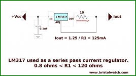
The LM317 (CC1) is a constant current source set up to output 125mA (1.25V/10R=.125A) as R22=10R.
So possibly Q3 is shorting or partially shorting and sinking too much current, exceeding the amount provided by CC1.
An explanation of the TL431/PNP shunt regulator circuit:
YouTube
If Q3 is OK, then possibly CC1 is not operating properly and not delivering enough current.
But I would suggest taking Q3 out and check it or replacing it first.
Ben
PS: Another possibility - a leaky capacitor, but I would check out Q3 first. What resistance do you measure across V-15 and Gnd? And compare with your other board?
Attachments
Last edited:
Hi Greg,
The LM317 (CC1) is a constant current source set up to output 125mA (1.25V/10R=.125A) as R22=10R.
So possibly Q3 is shorting or partially shorting and sinking too much current, exceeding the amount provided by CC1.
An explanation of the TL431/PNP shunt regulator circuit:
YouTube
If Q3 is OK, then possibly CC1 is not operating properly and not delivering enough current.
But I would suggest taking Q3 out and check it or replacing it first.
Ben
PS: Another possibility - a leaky capacitor, but I would check out Q3 first. What resistance do you measure across V-15 and Gnd? And compare with your other board?
Ben,
I just pulled Q3, voltage finally jumped up to ~17.5, then I dropped a new one in and voila, -15.01!
I have a chip installed now and letting it warm up and see if the voltages hold. So far, so good....
Great news. You're getting close.
Ben,
So, i plugged in my cheapie R1 chip this morning and biased out one side perfectly, the other side is got a huge offset of .4v, changing only by a few mV.
What I'm wondering if the R1 chip is actually a good test. Ryan did say the R1 would work, but I wonder if he ever tested it.
So, my joy was short lived. I don't want to plug my known-good S1 chip in without finding out why the R1 won't bias out on the one side.
I tried my S1 that I over-volted to -20v, and it's just exactly like the one one side of the R1 ~.43 volts.
So, not sure what to do at this point.
I've been checking the attenuators circuits, and everything seems good.
Cheers,
Greg
- Home
- Group Buys
- DIY TDA1541A PCB "D3"