I tried simulating the power supply, unfortunately MicroCap12 doesn't have the model for LM317.
IIRC, there's no good models for LM317 for Ltspice either.
I was going to see what direction voltage flow through the 22uF filmcaps. Reason being that usps seem to have lost the package with parts my friend sent me.
I do have some nice 22uF/12.5V Panasonic polymer polarized caps (in the same package-style as a tantalum cap ) that I could use.
If the caps need to be bipolar, I could two os-con (47uF, not sure how close the values need to the 22uF) back to back.
Or I can use Nichicon muse BP 22uF.
A cap with a low ESR is needed here but I would probably stay away from ceramics, as a second choice to the film cap id probably go for a polymer. Just make sure you correctly orientate the polarity of the cap.
Interestingly, there seems to be no need for a cap in this position when running in differential mode as I just found out tonight. The power supply sees a mostly constant current draw now that the waveforms are inverse to each other so there is no need to have a supply with such a low output impedance.
Last edited:
Its that's all you have then yes. But I cant say whether the diode attenuator will perform exatly the same.
I've got 5 LL4150, a ordering misstake on my part.
I've got about 300 LL4148.
A cap with a low ESR is needed here but I would probably stay away from ceramics, as a second choice to the film cap id probably go for a polymer. Just make sure you correctly orientate the polarity of the cap.
Interestingly, there seems to be no need for a cap in this position when running in differential mode as I just found out tonight. The power supply sees a mostly constant current draw now that the waveforms are inverse to each other so there is no need to have a supply with such a low output impedance.
The caps I have in mind first are Panasonic polymer caps, I believe these are the ones
Pana Polymer 22uF/12.5V
I also have some Nichicon Muse FG 47uF I could put back to back for a 23.5uF bipolar capacitor...no idea what that would do to ESR though.
The thing is, I don't know how to orient each of the 22uF/12.5V polymer caps. They are rather good, and now obsolete, don't wish to make them sparkle lol.
I've got SMD film caps to cover most needs, I thought, until I through your design came across a 22uF smd film cap that wasn't the size of a small car.
For the +4.5V, I'm thinking of using one of the small TPS7A4700 boards I had made year or two ago. Unfortunately that vreg was part of the stuff my friend sent me along with many of the parts for the I2S2SIM board.
You will be right on the 12.5V rating for the -15 reg. The minus goes to -15, -5, and positive to the +5. The pads closest to the supply pins are the ones connected to the corresponding supply pins. Just use the continuity mode on your multi-meter to confirm.
I think I tried some 100u Muse caps in that position and they didn't really do the job, they only made a very small improvement, but you could just give them a go anyway. Try without any cap there first so you can compare.
For the 4.5V reg you could also use a 5V reg and it will operate just fine. The TPS7A4700 should be ok, I never really noticed much if any change in SQ when going to a great efforts in supplying a really low noise source for the attenuator supply.
The caps I have in mind first are Panasonic polymer caps, I believe these are the ones
Pana Polymer 22uF/12.5V
I also have some Nichicon Muse FG 47uF I could put back to back for a 23.5uF bipolar capacitor...no idea what that would do to ESR though.
The thing is, I don't know how to orient each of the 22uF/12.5V polymer caps. They are rather good, and now obsolete, don't wish to make them sparkle lol.
I've got SMD film caps to cover most needs, I thought, until I through your design came across a 22uF smd film cap that wasn't the size of a small car.
For the +4.5V, I'm thinking of using one of the small TPS7A4700 boards I had made year or two ago. Unfortunately that vreg was part of the stuff my friend sent me along with many of the parts for the I2S2SIM board.
Hi Luke,
I had planned on doing a PCB for the CEN but now that im no longer using it I probably wont.
The current offset was very important in my experience, even a +-10mV offset caused audible distortion.
Re-clocking the DEM never really appealed to me because of the added complexity.
The real issue for the DEM was having a radio broadcasting transmitter inside of the DAC chip interfering with the timing circuitry resulting in a jittery output signal. Im not sure re-clocking the DEM will completely solve this issue. This is where running a DEM at 50Hz has a big advantage - no more EMI interfering with the timing of the output signal.
The Nichicon Muse BP I have are actually 100uF, I figured they were too large value. I could use one of those for the -15V and the the polymer 22uF/12.5V for +/-5V. Or if better, 100uF Muse BP on all three.You will be right on the 12.5V rating for the -15 reg. The minus goes to -15, -5, and positive to the +5. The pads closest to the supply pins are the ones connected to the corresponding supply pins. Just use the continuity mode on your multi-meter to confirm.
I think I tried some 100u Muse caps in that position and they didn't really do the job, they only made a very small improvement, but you could just give them a go anyway. Try without any cap there first so you can compare.
For the 4.5V reg you could also use a 5V reg and it will operate just fine. The TPS7A4700 should be ok, I never really noticed much if any change in SQ when going to a great efforts in supplying a really low noise source for the attenuator supply.
Having looked at the schematic, I figured I could use LL4150 in the attentuator circuit and LL4148 in the power supply? As I wrote, I have 5 lonely LL4150 due to an ordering error.
The TPS7A4700, I thought of using that as I have a few populated and tested boards I designed over a year ago.
I also made some dual rail TPS7AXXXX boards and some TPS7A3301 boards. I had some LT3042 boards made as well both with and without the BJT current "booster".
I had a period where I did a lot of vreg layouts in KiCad lol.
Do you know if anyone has used the i2s2sim board with the Audio-widget board? I have a couple of those and two xmos boards. The xmos I'd rather use as USB to spdif.
Btw, my compliments on nicely done boards. Not too densely populated. Very nice.
Thanks Ryan. What is your i/v of choice now?
My IV of choice would have to be what im using now - a hand wound resistor for IV and a transformer for the voltage gain.
The Nichicon Muse BP I have are actually 100uF, I figured they were too large value. I could use one of those for the -15V and the the polymer 22uF/12.5V for +/-5V. Or if better, 100uF Muse BP on all three.
A large value will improve the low impedance in to the lower bass frequencies, but the higher ESR will probably still be the bottle neck. C20 will see exactly 12.5V, might be worth taking the risk and use the polymer 22uF/12.5V - Ill leave that up to you.
Having looked at the schematic, I figured I could use LL4150 in the attentuator circuit and LL4148 in the power supply? As I wrote, I have 5 lonely LL4150 due to an ordering error.
Yeah do that.
The TPS7A4700, I thought of using that as I have a few populated and tested boards I designed over a year ago.
I also made some dual rail TPS7AXXXX boards and some TPS7A3301 boards. I had some LT3042 boards made as well both with and without the BJT current "booster".
I had a period where I did a lot of vreg layouts in KiCad lol.
If you've got them you might as well put them to good use!
Do you know if anyone has used the i2s2sim board with the Audio-widget board? I have a couple of those and two xmos boards. The xmos I'd rather use as USB to spdif.
Not familiar with that board sorry, maybe someone else will be.
Btw, my compliments on nicely done boards. Not too densely populated. Very nice.
Thanks very much, I put a lot of effort into the design.
")
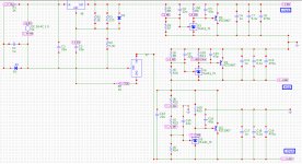
Hey, I finally found a model that worked and was able to simulate the D3 Power Supply, very nice and very close to spot on the target voltages.
BTW, I did the sim with 4148 diodes.
You could simulate the different types of caps you have and see what the output impedance is.
You could simulate the different types of caps you have and see what the output impedance is.
Being new at Micro-Cap12, that is currently beyond my ability.
I have, of course, not yet read the manual...
Being new at Micro-Cap12, that is currently beyond my ability.
I have, of course, not yet read the manual...
Ok, Ill have a go in LTspice, not quite sure what the ESR of the caps your using are though. Ill estimate a few numbers to get an idea of the change in performance.
Ok, Ill have a go in LTspice, not quite sure what the ESR of the caps your using are though. Ill estimate a few numbers to get an idea of the change in performance.
I think it's in the datasheet I linked a few posts back.
IIRC, it was something like 30mOhm.
Could be way off as I am in bed with a fever...one of the percs of having a 3yo in preschool.
I think it's in the datasheet I linked a few posts back.
IIRC, it was something like 30mOhm.
Could be way off as I am in bed with a fever...one of the percs of having a 3yo in preschool.
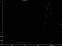
I dont have very accurate models of either cap, but you can at least get an idea of whats going on, the blue trace is the zout of a cap with a high ESR and ESL, the green trace is a cap like the PMLCAP with low ESR and ESL.
The joys of parenthood. At least with all those germs they bring home are strengthening your immune system!
Hope you get over it soon so you can work on your DAC. Attachments
Last edited:
I dont have very accurate models of either cap, but you can at least get an idea of whats going on, the blue trace is the zout of a cap with a high ESR and ESL, the green trace is a cap like the PMLCAP with low ESR and ESL.
The joys of parenthood. At least with all those germs they bring home are strengthening your immune system!
The lower ESR ESL has lower zout higher up in frequensie.
There are a few things I need to get built, I have less time since her mother and I separated as I have my daughter a couple of hours every day. She and her mother live about 20 meters from me.
I have 3x Red Baron V5 fully populated, one Analog Metric with carefully chosen parts and a jfet/triode I/V and output. Did the best I could given that design.
I haven't gotten around to testing the other DAC's, including one dual PCM1794 "barebone" I designed (everything but the D/A's and surrounding parts has to be added off board), another dual PCM1794 fleabay thing with parts swapped for better ones, one 16x TDA1543 NOS. And a couple of ESS DAC's.
Before the separation, I couldn't have the stereo system up as my girl was too small to know not to touch and my then fiancé didn't want dac's, preamps, poweramps etc "cluttering" up the livingroom.
Germs...I believe this is the forth or fifth cold and she's been at preschool one semester.
You think the Pana polymer will survive being right on the edge of the tolerated 12.5V?
Speaking of parts, I got 20x LL4150 in the mail today. As I didn't order them, I guess one of my Swedish friends (sent domesticly) took pity on me lol.
Thanks for doing the sim
No problem, sims are one thing, but how it sounds is obviously a tad more important, and those PMLCAPS really are SOTA and sound great in that position.
Those Pana Polymer caps might have some current leakage running them at their max voltage rating which in turn will effect the voltage reference for the TL431 - thus givng an inaccurate output voltage. But then again they may be fine, i'd give them a go if I had nothing else.
Those Pana Polymer caps might have some current leakage running them at their max voltage rating which in turn will effect the voltage reference for the TL431 - thus givng an inaccurate output voltage. But then again they may be fine, i'd give them a go if I had nothing else.
No problem, sims are one thing, but how it sounds is obviously a tad more important, and those PMLCAPS really are SOTA and sound great in that position.
Those Pana Polymer caps might have some current leakage running them at their max voltage rating which in turn will effect the voltage reference for the TL431 - thus givng an inaccurate output voltage. But then again they may be fine, i'd give them a go if I had nothing else.
Who knows the parcel my friend sent could arrive eventually, not holding my breath though as there's not been any tracking update since Nov 5th.
Sent via USPS and apparently they aren't that good at not loosing parcels or having them detoured (had a parcel I thought lost show up after a detour to Australia...that's quite a long way from Sweden.)
I do have some other options, like the 100uF Muse BP, and some others.
You figured polymer caps would be best?
- Home
- Group Buys
- DIY TDA1541A PCB "D3"