Sorry , for the delay .
I'm kind of stucked because I did get requests to use bigger heatsinks for the recifier diodes . Some guys want to use this supply for Class A amps .
I could draw a new layout for using bigger powerfets and bigger heatsinks (diodes) or layout the board to use the main heatsink but this gonna get a big board .
What do you think guys of using a seperate recifier board ?
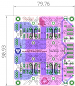
Hi meanman, nice to hear from you finally. The design you show in post #57 is OK with me, but you could maybe slightly increase the PCB size to allow for the bigger deeper TO220 heatsink sizes - don't forget they make these up to around 63mm high or so.
Also to make it more universal, you could then extend the tracks around the +/- pass transistors towards the edge of the PCB to alternatively mount these off the board on the main amp heatsinks with legs bent up to solder to the PCB, this would then allow these devices to be directly mounted on the PCB with a choice of TO220 heatsink size or off the board on the external amp heatsink for larger currents as required by Class A amps. I think adequately sized TO-220 heatsinks for the rectifiers would be OK for all solutions. Hope that makes sense for you.
regards,
Gary..
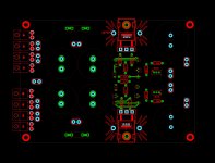
If you keep the diodes close to the smoothing caps and the common connection between the caps wide track, this'll reduce the 'noise' of the diode switching to a minimum and localize the charging current spikes
You might consider adding some extra donuts for the low dropout SMD diode rectifier pcbs and/or the 'new' active rectifier bridges that don't actually need any heatsinks at all.
You might consider adding some extra donuts for the low dropout SMD diode rectifier pcbs and/or the 'new' active rectifier bridges that don't actually need any heatsinks at all.
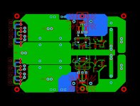
The design from Prasi is very flexible as it gives the builder the choice of either TO220 or TO147 sized diodes as well as the 2 different heat sink widths to accommodate what ever currents are being catered for. One then can choose the relevant height of heat sink to allow for anticipated device power dissipation.
Hi meanman and thanks for putting the effort into this design and GB - appreciated.
If I may say so, I think you're in danger of chasing a universal design, which I think is never going to be achievable - someone will always want some little extra. I suggest you settle on a design that achieves a set of parameters, such as its current capability, heatsinking configuration, etc. that meet your requirements and then go with it. People can then choose to work within those parameters or do something else.
Just my penn'orth.
I know , have to draw a line somewhere or I never can finish .
So, barring the need to correct any actual errors that might slip in, I suggest that the next iteration of your board is the one to go with for the group buy. I am, of course, assuming it will meet your own personal needs.
wow quick read only through this so far gonna have to go through again as soon as i have time w/o kid duty to understand the goals/merits and costs for this possible since it does not appear closed yet
meanwhile if anyone has gone through all of thisnd can summarize that would be nice and handy for anyone just coming along and/or for future reference etc
meanwhile if anyone has gone through all of thisnd can summarize that would be nice and handy for anyone just coming along and/or for future reference etc
Earthquake /UK / 4 boards
arthur / HK / 8 boards
markus22ch /Swiss / 4 boards
KVP / Belgium / 4 boards
vasillis / Greece : 4 boards
odie1472 :Brunie / 4 boards
Mindfunk / Germany/ 4 boards
nautibuoy/UK/4 boards
Wot4Pilot/UK/2 boards
aspringv/Australia/2 boards
jacques antoine/France/2 boards
yoaudio/USA/6 boards
Johnny2Bad/ 2 boards
kaliwraith/USA/2 boards
shattered_dream /germany/2 boards
JimS/USA/ 3 boards
Juntuin/Finland/2 pcb's
MD_Stryker/USA/ 2 boards
emynet/Italy/ 2 boards
vitalica / 4 boards
dabore84 / NL / 2 boards
gary s / Australia / 2 boards
Ian Greenhalgh / UK / 4 boards
Total : 75

Can you post the schematic and BOM as your pcb design stands at the moment thanks.
size etc and as others have asked a single posting with specs details etc etc as much as possible ans no where yt have i found info on an actual cost either unless that info is a state secret etc im sue naby would want to know
also a q some prolly didnt think of but assuming these are being produce by X chinese factory etc it might be worth checking if its possible and probably cheaper to drop ship via china post etc than to ship to one personand then remail esp since basic mail for small items from china etc seems so much cheape than many other places
also depending on location it might be worth combining boards for ppl in the same country ito one pkg. I am in southern ontario Canuckistan for example which is close to the GTA but someonr insay Vancouver BC would not be local... (but niagra falls NY is lol)) anyhow just a thought
also as a GB.. anyone thought of an option for this fully or partially populated? might be worth investigating as one possible way to help save via bulk etc
Last edited:
- Home
- Group Buys
- 4 caps Mr Evil's Capacitance Multiplier Power Supply PCB