Anyone in for a testrun of a LTC3784 2/4 phase boost converter?
The converter ist meant to power a class-d amplifier from different sources and is intended for use with the TPA3151 or TPA3255 but not restricted to this.

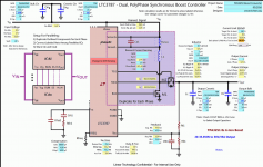
Design is made for either 2 or 4 phase operation at ~250kHz.
Input Voltage is 10V minimum up to the desired output voltage with pass through if the input voltage is higher than the output. This is especially usefull when using a 10s lithium pack to power an amp at 36V native voltage. As long as the pack voltage is higher than 36V (42V max for 10 cells) it is passed through the converter for best efficiency. When the input drops below 36V the converter starts boosting. Efficiency is in the range 90-98%.
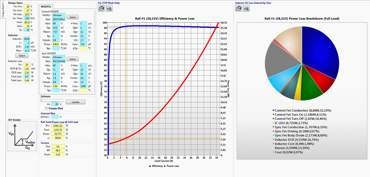
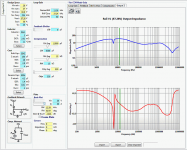
Simulations are done for 1000W cont. load:
2 phase:
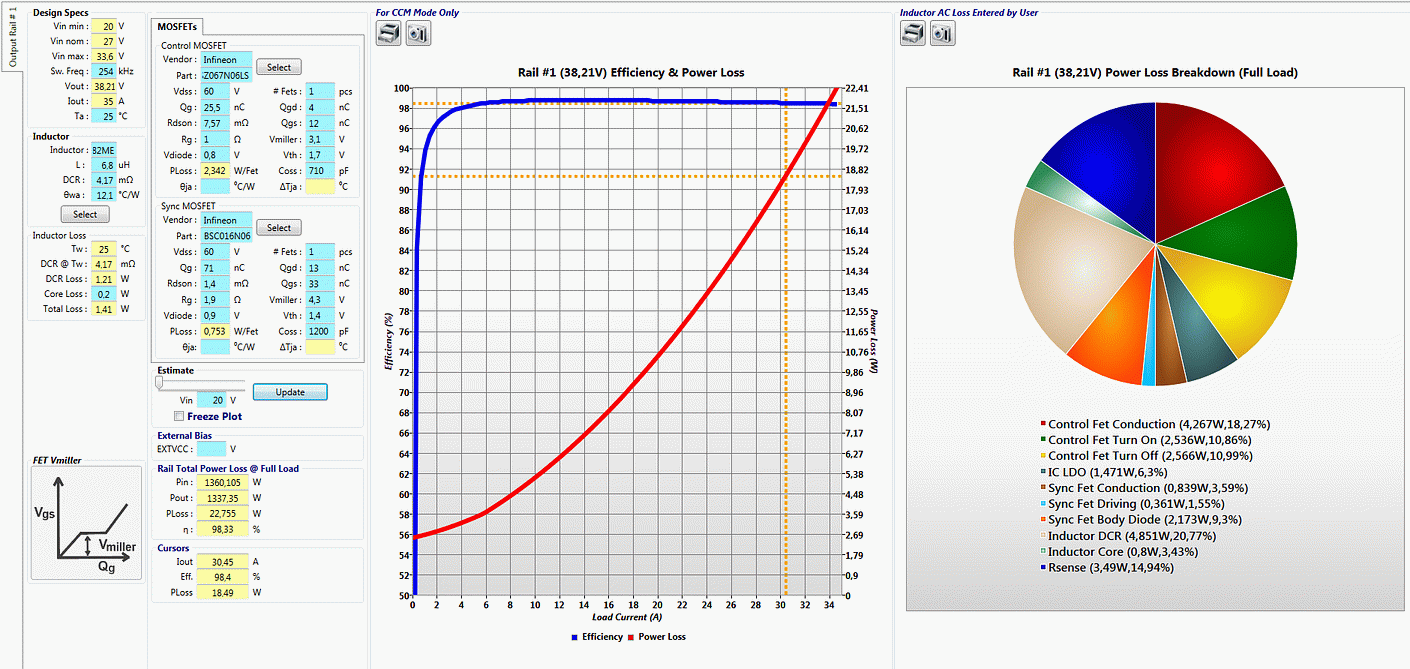
4 phase:
Initial design parameters:
600W cont. output
1200W peak output (thermally limited)
regulation loop bandwidth > 10kHz
4 phase operation for 12V SLA battery input with up to 30A per phase
2/4 phase operation for voltages greater than 24V like SLA in series or lithium battery packs
100*100mm in size
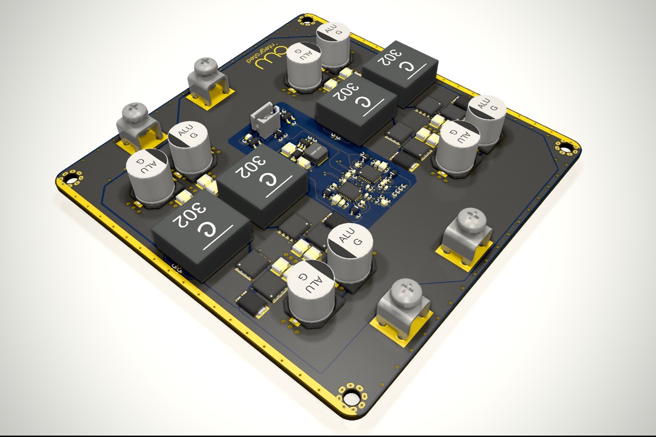
The PCB is a 4 layer board with 100*100mm in dimension. The design is finished and several use cases are available for simulation in LTSpice and LTpowerCAD.
Motivation:
Even if there are boost converters available for "cheap" from Aliexpress/TaoBao/Ebay, these are mainly limited to about 30A cont. input current and single phase (hard switching) with lots of radiated EMI (by design). With 10V input voltage under load, these run out of "ompf" at about 300W input power. The 2/4 phase concept shown here is able to push 30A per phase so 1200W from 10V input should be possible.
Groupbuy intent:
This groupbuy is for a bare PCB with schematics, BOM and assembly instructions. I want to order a minimum of 10pcbs but actually need less so thats where you can jump in.
For the first run i'd order standard 1.6mm, 4 layer, 1oz, green silk board with HASL. The price for one PCB is roughly 7€ then. If there's enough interest, we may order ENIG (2oz.) boards with Red or Blue silkscreen.
International shipping is 4€ untracked or 6.20€ tracked with "Deutsche Post" from Germany.
Risks:
The design is practically untested (as usual for the first run), so their is a small risk that some things need manual patches. Having said that, the implementation is working in simulation (LTSpice, LTpowerCAD), so the chances are high it works out of the box. Things need tweaking are regulation bandwidth and compensation.
I've done several designs for class-D, dsp, audio, etc. in the past, so this is not my first project. You may check on 360customs.de which is my uncommercial build blog.
Best regards,
Christian
The converter ist meant to power a class-d amplifier from different sources and is intended for use with the TPA3151 or TPA3255 but not restricted to this.
Design is made for either 2 or 4 phase operation at ~250kHz.
Input Voltage is 10V minimum up to the desired output voltage with pass through if the input voltage is higher than the output. This is especially usefull when using a 10s lithium pack to power an amp at 36V native voltage. As long as the pack voltage is higher than 36V (42V max for 10 cells) it is passed through the converter for best efficiency. When the input drops below 36V the converter starts boosting. Efficiency is in the range 90-98%.
Simulations are done for 1000W cont. load:
2 phase:
4 phase:
Initial design parameters:
600W cont. output
1200W peak output (thermally limited)
regulation loop bandwidth > 10kHz
4 phase operation for 12V SLA battery input with up to 30A per phase
2/4 phase operation for voltages greater than 24V like SLA in series or lithium battery packs
100*100mm in size
The PCB is a 4 layer board with 100*100mm in dimension. The design is finished and several use cases are available for simulation in LTSpice and LTpowerCAD.
Motivation:
Even if there are boost converters available for "cheap" from Aliexpress/TaoBao/Ebay, these are mainly limited to about 30A cont. input current and single phase (hard switching) with lots of radiated EMI (by design). With 10V input voltage under load, these run out of "ompf" at about 300W input power. The 2/4 phase concept shown here is able to push 30A per phase so 1200W from 10V input should be possible.
Groupbuy intent:
This groupbuy is for a bare PCB with schematics, BOM and assembly instructions. I want to order a minimum of 10pcbs but actually need less so thats where you can jump in.
For the first run i'd order standard 1.6mm, 4 layer, 1oz, green silk board with HASL. The price for one PCB is roughly 7€ then. If there's enough interest, we may order ENIG (2oz.) boards with Red or Blue silkscreen.
International shipping is 4€ untracked or 6.20€ tracked with "Deutsche Post" from Germany.
Risks:
The design is practically untested (as usual for the first run), so their is a small risk that some things need manual patches. Having said that, the implementation is working in simulation (LTSpice, LTpowerCAD), so the chances are high it works out of the box. Things need tweaking are regulation bandwidth and compensation.
I've done several designs for class-D, dsp, audio, etc. in the past, so this is not my first project. You may check on 360customs.de which is my uncommercial build blog.
Best regards,
Christian
Attachments


Last edited:
Nice project Dr Mord! Can this be a dual rail supply?
In any event, you can out me down for a pair of boards.
---
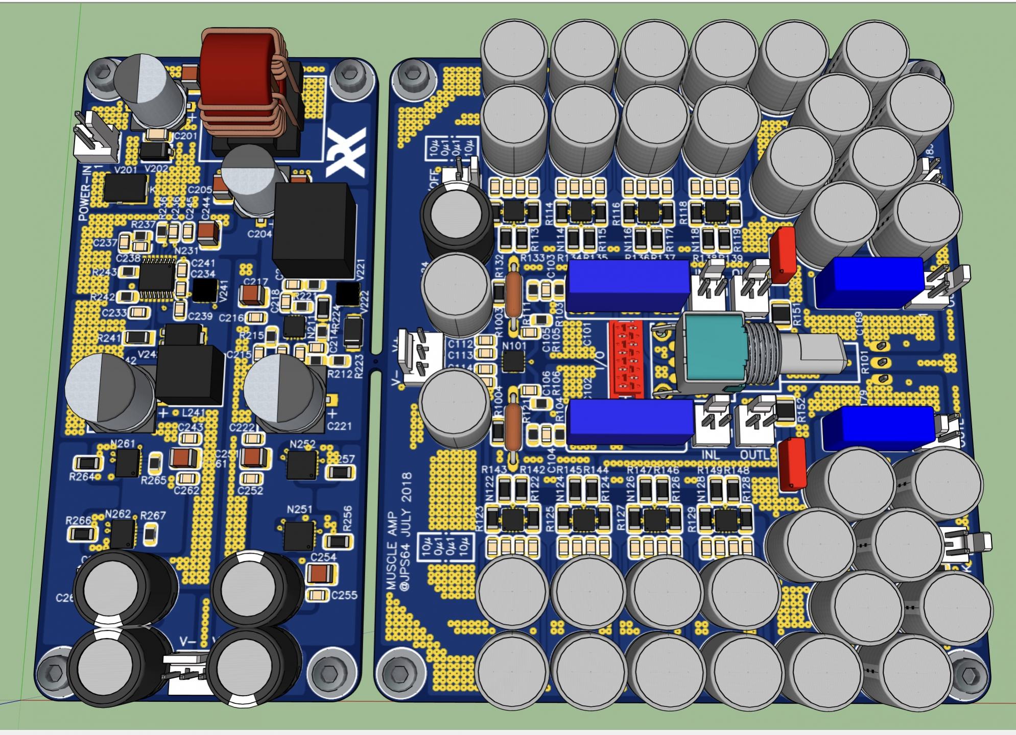
I recently have been working with JPS64 to make a simple way to get really clean +/-18v at 1amp to 2amps for smaller amps and preamps. All powered from 8v to 18v wallwart without need for dealing with mains AC voltages and dangers associated with linear transformers.
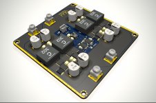
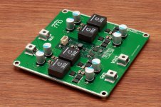
Here is a design for a 1amp supply with TPS7Axxx low noise LDO's (it's the middle rectangular board):
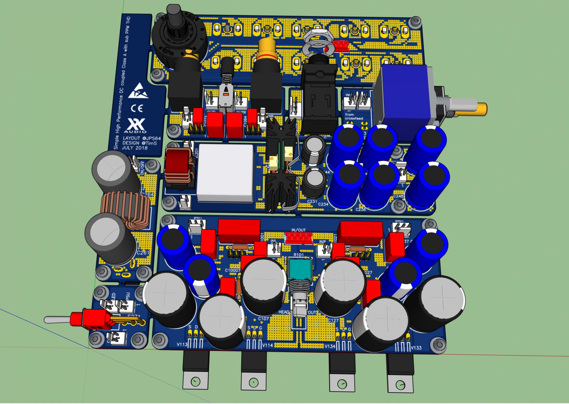
Simple High Performance DC Coupled Class A HPA with sub PPM THD
Here is a 2amp version with some different parts (the rectangular board on left):
In any event, you can out me down for a pair of boards.
---
I recently have been working with JPS64 to make a simple way to get really clean +/-18v at 1amp to 2amps for smaller amps and preamps. All powered from 8v to 18v wallwart without need for dealing with mains AC voltages and dangers associated with linear transformers.
Here is a design for a 1amp supply with TPS7Axxx low noise LDO's (it's the middle rectangular board):
Simple High Performance DC Coupled Class A HPA with sub PPM THD
Here is a 2amp version with some different parts (the rectangular board on left):
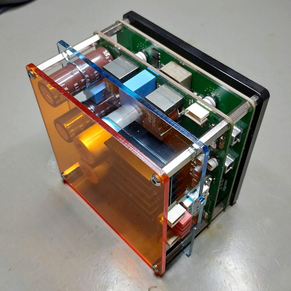
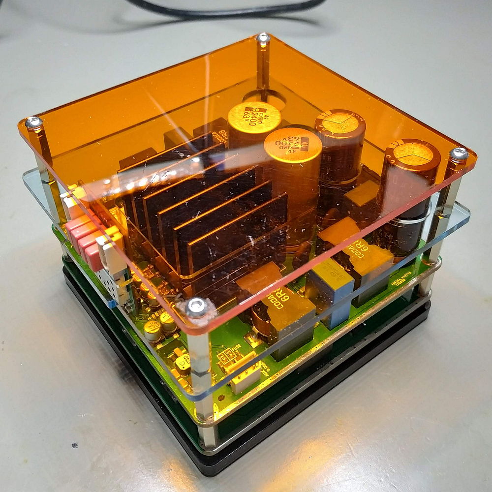
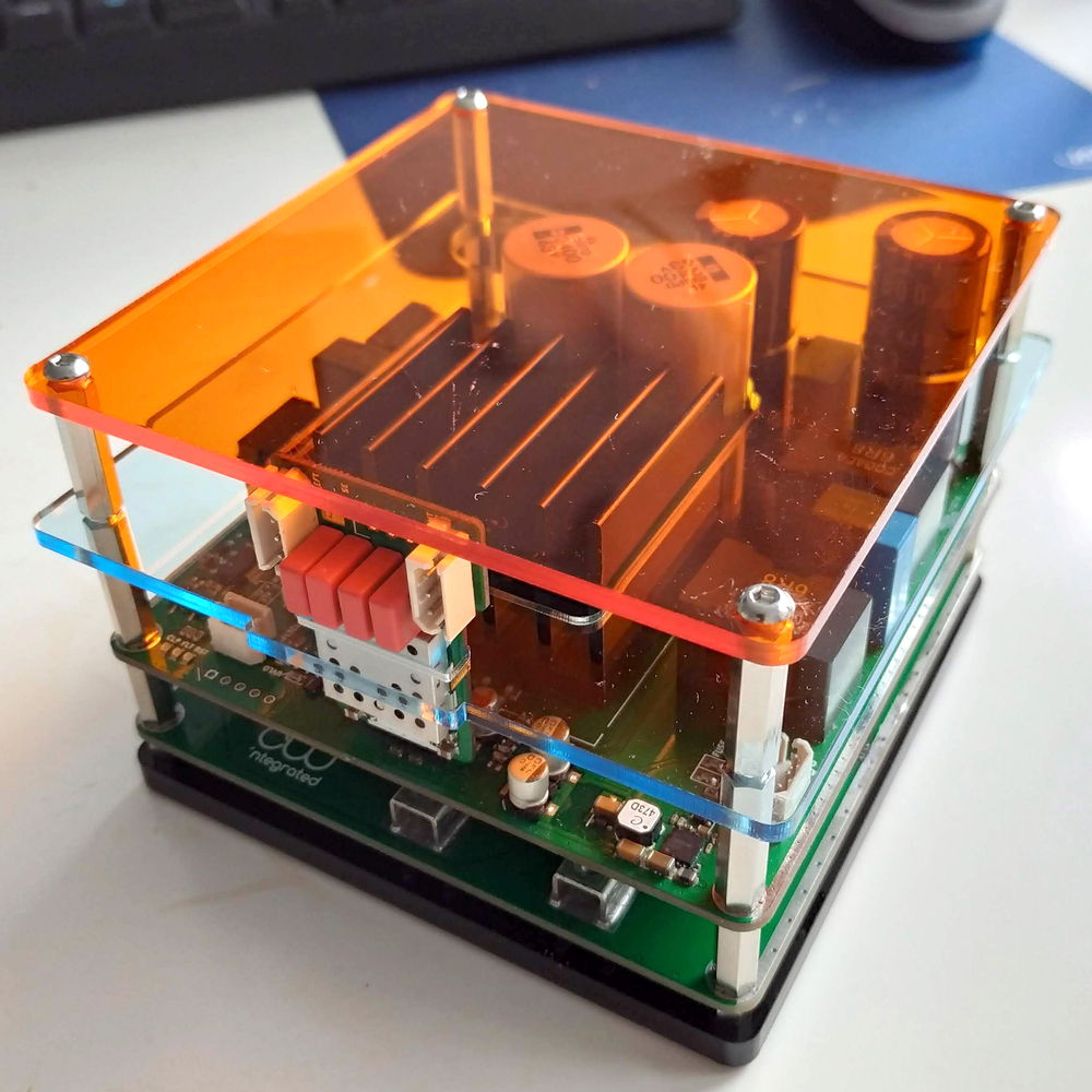
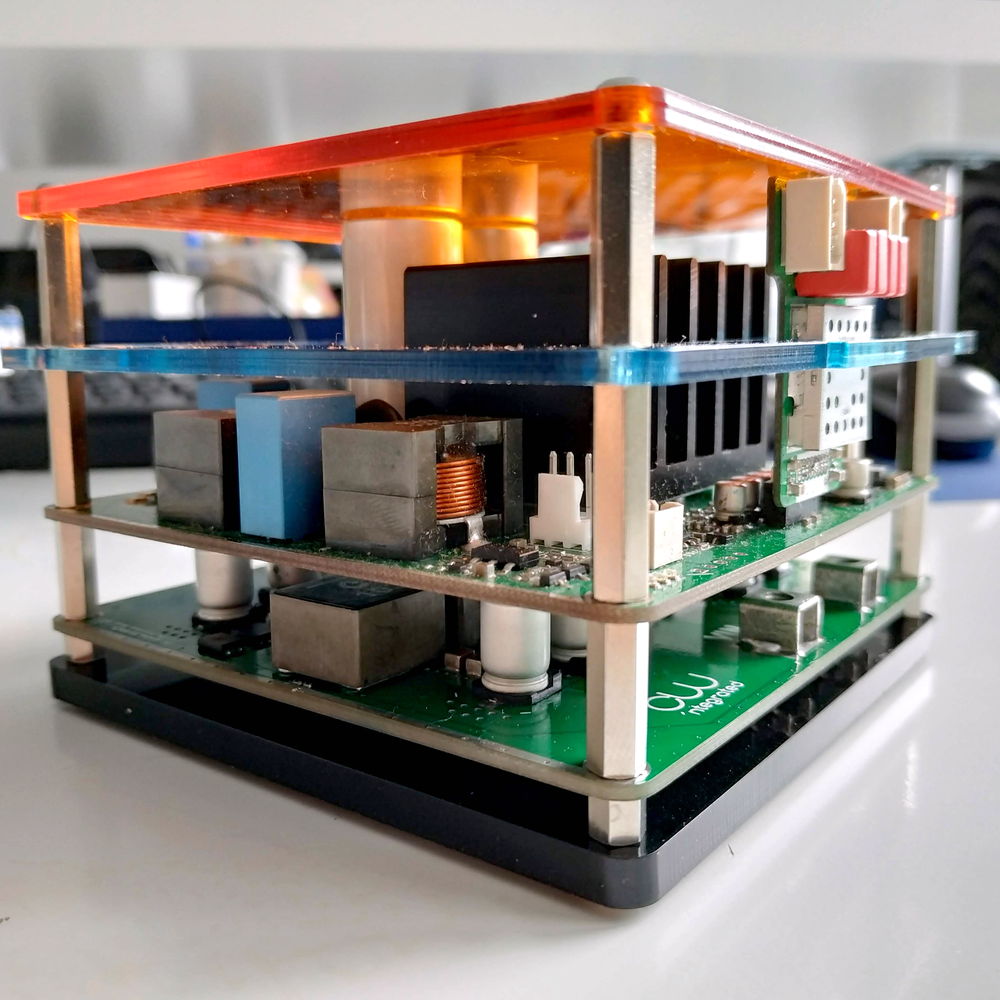
So, in the end they found together, TPA3255 2.1 100x100mm system in direct contact with the 1200W 4-phase LTC3784 boost-converter board, making it possible to go the distance with even only having 10V at the input to put out 600Wrms. As this asks for 1200W power into the amp and an realistic efficiency of 92% from the boost converter, this setup is asking for 130A at the 10V input. (Things get much easier when using a 36V supply) For the AFE module and bulk caps there is a mounting holder within half of the height to make good support for stability while driving with the bike. The whole thing measures 110x110x70mm, i'd call this a power-brick.
Bike? The bike with the actual setup, TPA3255 + 3x12V SLA system...
Youtube: YouTube
Bike? The bike with the actual setup, TPA3255 + 3x12V SLA system...
Youtube: YouTube
- Status
- This old topic is closed. If you want to reopen this topic, contact a moderator using the "Report Post" button.
- Home
- Group Buys
- LTC3784 2/4-Phase Boost Converter for up to 55V Output 600/1200W (TPA3251, TPA3255)