If you look carefully at the photo on post 1 you can see which pins go to which pins. Follow the yellow wire - that’s +ve 18v.
The schematic will also give you the correct pin and reference pin 1.
Thanks X.
The problem was that I prefabbed 1:1 leads expecting the modules to be 'murphy-proof' (I need all the help I can get sometimes!)
 .
. Easily fixed by installing X112/113 on the amp board rotated 180 degrees.
Hoping to get some sound through it tomorrow!
Glad you got that sorted out and hope no permanent damage was done. What is the quiescent bias current? If that is flowing correctly, you will most likely have a functional amp. Since DC offset appears close to zero, it’s probably all good.
I think in the future, for DC power inputs, we will add a label of + and GND and - to the silkscreen to ensure this sort of stuff doesn’t happen. This seems to happen all too often. Even on my DCA which is just single polarity people mix those up. All one has to do is check for continuity with the ground plane. But that’s an extra step.
I think in the future, for DC power inputs, we will add a label of + and GND and - to the silkscreen to ensure this sort of stuff doesn’t happen. This seems to happen all too often. Even on my DCA which is just single polarity people mix those up. All one has to do is check for continuity with the ground plane. But that’s an extra step.
Last edited:
Just the damaged BJTs it seems.
Measured 0.31v over R117 and R137, so 0.31/2.2 = 141mA bias.
I temporarily connected up the audio side and used a pair of knock off 'Beats' headphones and hit the power button...
And she's alive
Both channels sound great (even with a crappy audio setup - croc clips and all!). There is definitely a decent amount of detail in the lower ranges and the circuit really does sound good as others have said. Can't wait to get it properly loomed.
One thing I don't like is the DC dump to headphones when the amp is switched off. Is that a normal behaviour?
No DC on the output while switched on.
When power switched off, DC charges up to 1.25v, holds for a couple of seconds then dissipates.
The headphones make crackling sound as the voltage dissipates.
This is on both channels.
I'm using the CLC board if that makes any difference (could the inductor do that?)
Edit: no, just bypassed the CLC and switch boards and same.
Otherwise the amp is silent in operation (noise wise) and no appreciable DC offset.
Last edited:
As I gave away both of my amps, I can’t test this anymore but sounds like it may be an inherent “feature” of this topology. So perhaps adding a DC protect circuit or a turn on/off relay that instantly disconnects phones moment power switch is turned off. I will have to ask Byrtt if his amp exhibits this. In the meantime, just leave the amp on - it’s not bad for it, and in fact will last longer than switching on and off (if you don’t mind the continuous 10w draw) .
Hi Avtech,
I checked with Byrtt and he tried turning off the unit with headphones plugged in. There is no turn off thump, just a gradual decrease in sound to nothingness.
However, if you unplug the headphone and plug it back in while it is in process of turning off and discharging, you may hear a mild thump. He measured it and it is about 0.22v. This persists for a several minutes as the caps discharge.
I checked with Byrtt and he tried turning off the unit with headphones plugged in. There is no turn off thump, just a gradual decrease in sound to nothingness.
...never tried a power off with head phones connected so had to set it up and do the test, didn’t notice what I call a real DC thumb at power off just little bit of sound stream change for one second or so and then output level drops to a very low level for about 15-30 seconds before sound stream dies totally...
However, if you unplug the headphone and plug it back in while it is in process of turning off and discharging, you may hear a mild thump. He measured it and it is about 0.22v. This persists for a several minutes as the caps discharge.
Thanks for checking that out. In the meantime, I installed a DC protection module.
I seem to have a problem somewhere. Although I have music, I also have a wicked 50Hz hum and AC on the chassis.
It is extreme when using an isolated plug pack - I am getting 75v+ on the chassis despite there being no continuity between chassis and Neg. The lab supply has 5v ac WRT GND and this is present on the chassis when I use that to power it up.
I cant explain how it gets there.
Oh and when I touch the chassis, the frequency doubles
Hi Avtech,
This amp was designed to be absolutely hum-free if setup properly. You have an inadvertent connection to ground somewhere and the 75v is extreme - seems like you have a live chassis - be careful!
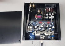
Please sketch a block diagram showing connections between the amp and the chassis and power supply, etc all knobs, jacks, swithes, pots should be shown. Are you using isolated RCA jacks and isolated headphone out jacks? There should be a plastic insulator ring around the GND on the headphone jack and the RCA input. The volume pot is another place - cheap pots are metal shell and that is connected to the gnd of the pot. Also take several closeup photos from multiple angles to show how everything is laid out. Ground loops are troubling - but with careful work, can be fixed.
One question is how are you supplying the 12v input DC to the amp? I used an isolated 5.5mm barrel jack. The GND on the DC input should not touch the case. It will be isolated internally via the DC-DC converter chip inside. That is how any mains or high DC ground loops care isolated from the amp.
This amp was designed to be absolutely hum-free if setup properly. You have an inadvertent connection to ground somewhere and the 75v is extreme - seems like you have a live chassis - be careful!
Please sketch a block diagram showing connections between the amp and the chassis and power supply, etc all knobs, jacks, swithes, pots should be shown. Are you using isolated RCA jacks and isolated headphone out jacks? There should be a plastic insulator ring around the GND on the headphone jack and the RCA input. The volume pot is another place - cheap pots are metal shell and that is connected to the gnd of the pot. Also take several closeup photos from multiple angles to show how everything is laid out. Ground loops are troubling - but with careful work, can be fixed.
One question is how are you supplying the 12v input DC to the amp? I used an isolated 5.5mm barrel jack. The GND on the DC input should not touch the case. It will be isolated internally via the DC-DC converter chip inside. That is how any mains or high DC ground loops care isolated from the amp.
Sorry for the delay in replying (and the forthcoming wall of text), I've been trying to fault find over the weekend to figure out what is going on.
The amp is set up as follows:
Power:
12-18VDC* -> CLC Board -> Switch -> CLC Board ->AMP & to DC Protect board.
Input:
RCA -> Twisted Pairs / unconnected shield -> 10k Vol Board -> AMP
Output:
AMP -> Twisted Pairs / unconnected shield -> DC Protect Board -> H/Phone Out Board
Volume Pot is touching Chassis - but leaving it floating has no effect, and no continuity on board to chassis.
H/Phone out jack is isolated from chassis.
No continuity between power switch body and pins.
Power regs and their heatsinks are isolated.
There are no connections between chassis and any of the boards.
There is no connection to earth and the DC jack is isolated.
* 12VDC 2A SMPS 'Wall Wart' (Multiple tried) / 12-18VDC 10A Bench Supply
*****************
When connected up to the lab supply:
I get a low hum.
The 2 input capacitors are very sensitive to touch.
If I touch the top case of the capacitors on the Traco board, the noise level drops.
If I touch the H/Phone output GND, the noise level drops.
When using a switch mode supply:
I get a loud hum.
Same as above.. but if I touch the chassis, I get 'Bwaaaaaaaaaaaaaa'.
*****************
There is no connection between chassis and earth.
When measuring the chassis WRT to House Earth, the lab supply measures about 6VAC, the SMPS shows 75-90VAC. I don't understand how there is a difference when I can find no continuity between chassis and Earth.
Any SMPS I use is horrifically worse than using the bench supply.
I'm pretty sure I have a nice big antenna between the RCA and the Input Vol board but I have not been able to find a combination of grounding that will kill the noise. I have tried various combinations of wires and shield connection points but I'm not winning this battle.
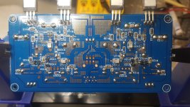
I've attached a photo of the latest layout.
(I have taken the DC protect out of circuit but this makes no difference. I have fed it with a different power source also but no change).
The amp is set up as follows:
Power:
12-18VDC* -> CLC Board -> Switch -> CLC Board ->AMP & to DC Protect board.
Input:
RCA -> Twisted Pairs / unconnected shield -> 10k Vol Board -> AMP
Output:
AMP -> Twisted Pairs / unconnected shield -> DC Protect Board -> H/Phone Out Board
Volume Pot is touching Chassis - but leaving it floating has no effect, and no continuity on board to chassis.
H/Phone out jack is isolated from chassis.
No continuity between power switch body and pins.
Power regs and their heatsinks are isolated.
There are no connections between chassis and any of the boards.
There is no connection to earth and the DC jack is isolated.
* 12VDC 2A SMPS 'Wall Wart' (Multiple tried) / 12-18VDC 10A Bench Supply
*****************
When connected up to the lab supply:
I get a low hum.
The 2 input capacitors are very sensitive to touch.
If I touch the top case of the capacitors on the Traco board, the noise level drops.
If I touch the H/Phone output GND, the noise level drops.
When using a switch mode supply:
I get a loud hum.
Same as above.. but if I touch the chassis, I get 'Bwaaaaaaaaaaaaaa'.
*****************
There is no connection between chassis and earth.
When measuring the chassis WRT to House Earth, the lab supply measures about 6VAC, the SMPS shows 75-90VAC. I don't understand how there is a difference when I can find no continuity between chassis and Earth.
Any SMPS I use is horrifically worse than using the bench supply.
I'm pretty sure I have a nice big antenna between the RCA and the Input Vol board but I have not been able to find a combination of grounding that will kill the noise. I have tried various combinations of wires and shield connection points but I'm not winning this battle.
I've attached a photo of the latest layout.
(I have taken the DC protect out of circuit but this makes no difference. I have fed it with a different power source also but no change).
Attachments
How is your source grounded? Is the hum bad when source is not connected? Try adding a connection from amp board ground to chassis via a 1W 10ohm and pair of diodes (typical GLB) and connect chassis to mains earth ground.
To debug, remove connections from all parts except main and PSU. Connect HP jack directly to board not touching the case.
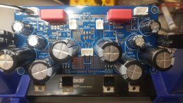
Do you have insulating shoulder washers on your MOSFETs? Those screws look really big. The washers have to insulate the shaft of the screw as well as the cap.
To debug, remove connections from all parts except main and PSU. Connect HP jack directly to board not touching the case.
Do you have insulating shoulder washers on your MOSFETs? Those screws look really big. The washers have to insulate the shaft of the screw as well as the cap.
Last edited:
Problem is I am using isolated supply so mains earth ground not readily available.
I'm using a mobile phone 3.5mm jack to RCA to test. Does this amp require a grounded input device?
I'll try the resistors tomorrow, thanks.
MOSFETs are isolated with the insulating pad and the shouldered plastic bushing. Nil continuity between fet and chassis. The screws are M3 10mm through the aluminium spacer into the chassis.
Last edited:
With the amp powered off and not connected to a source or headphone, measure the resistance between the case and signal ground.
You may have a cold solder connection from one of your RCA gnd to the volume pot, etc. When touching the case causes a large change in noise or hum, it indicates an improper or open circuit on one of your ground returns. You may have a wire strain issue and one of the ground wires is internally broken.
I like to use small RG170 coax cable from the RCA jack to the pot and from the pot to the board. I find this reduces noise pickup as the shield is grounded and signal wire is inside.
Open circuit between case and signal ground. Wires are all without tension and buzz out fine.
I've finally managed to kill the noise. I had to:
1. Connect PSU input 0V directly to chassis. - This made the amp silent except when touching anything from the (floating) Source to RCA.
2. Loop breakers on both audio grounds to the connection made at 1. (1n400x anti-parallel, 1W 10R, 100nF). - I get a very faint buzz if I touch the mobile phone (cell phone) but otherwise the amp is now dead silent and sounds great again.
I'll take a look at the PSU when I get a chance - perhaps there is something wrong with the resistors that tie Audio Gnd and Power Gnd. I probably cooked them..
But for now, thanks X for all your help getting this sorted. And thank Brytt for taking the trouble to test out his amp for my benefit.

A pot wiper should be able to be fully shorted to gnd (0 ohms) on the fully CCW turn - thus forcing the input volume to zero. If you gnd the input, I assume the sound goes away? Perhaps, your pot is hitting a mechanical stop before it fully goes to gnd? Or, since you added 10R gnd lift to the RCA, it can never go to zero?
I swapped in the MELF 2R7 resistors - 0207 resistors *just* fit on the pads, but it looks pretty ugly. On the other hand... hey, it fit. also swapped R108 & 103 to carbon resistors. will have to listen and see if I can hear any differences
I've really been liking the sound of this amp, more than the DCA or the AKSA HPA!
I've really been liking the sound of this amp, more than the DCA or the AKSA HPA!
- Home
- Group Buys
- Simple High Performance DC Coupled Class A HPA with sub PPM THD