I still need to do the mods on mine, but it is reasonably close, and I found a lot of gains by preventing common mode noise from the switcher in my PC from getting back to the line.. (Medical grade isolation transformer) The NUC is much quieter than what it replaced. The RTX does not share the same power connection as the NUC or monitor.
I also have electrostatic shielding under the work space which is grounded to the RTX, these days I am able to work on phono stage designs and get good measurements with 5mV into the DUT, was always a problem before.
I also have electrostatic shielding under the work space which is grounded to the RTX, these days I am able to work on phono stage designs and get good measurements with 5mV into the DUT, was always a problem before.
XLR-BNC adapter
The RTX only has XLR inputs to the analyzer, so if you do single-ended measurements you need an adapter. These are standard products and most people have them in their parts box probably.
But there can be a catch, which I ran into. For XLR, pin 2 & pin 3 are the signal pins, pin 1 is the equipment chassis connection. You should never connect pin 1 to signal ground as this normally causes noise on the signal lines.
In XLR-BNC adapters one of the signal lines, normally pin 3, is interconnected to pin 1, opening up the possibility of ground loops and noise.
What to do?
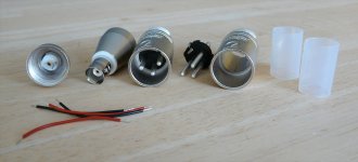
Neutrik (as often) to the rescue. They sell XLR-BNC adapters that are un-assembled where you can wire the internal connections as you want, complete with a pair of stripped short wires! See the attached picture. I build up a pair with the central BNC to pin 2 and the BNC 'ground' tag to pin 3. (The BNC 'chassis' is isolated from the XLR shell). I kept pin 1 internally unconnected; when you plug it into the RTX it connects to the chassis through the shell, and that is how it should be.
When you look for these adapters on the Neutrik website, you won't find them (at least I didn't); you only find NA2MBNC, which is internally wired with pin 3 and pin 1 interconnected.
But Mouser sells the unwired version as NA2MBNC-UW (UW stands for un-wired). The female version is NA2FBNC-UW.
Jan
The RTX only has XLR inputs to the analyzer, so if you do single-ended measurements you need an adapter. These are standard products and most people have them in their parts box probably.
But there can be a catch, which I ran into. For XLR, pin 2 & pin 3 are the signal pins, pin 1 is the equipment chassis connection. You should never connect pin 1 to signal ground as this normally causes noise on the signal lines.
In XLR-BNC adapters one of the signal lines, normally pin 3, is interconnected to pin 1, opening up the possibility of ground loops and noise.
What to do?
Neutrik (as often) to the rescue. They sell XLR-BNC adapters that are un-assembled where you can wire the internal connections as you want, complete with a pair of stripped short wires! See the attached picture. I build up a pair with the central BNC to pin 2 and the BNC 'ground' tag to pin 3. (The BNC 'chassis' is isolated from the XLR shell). I kept pin 1 internally unconnected; when you plug it into the RTX it connects to the chassis through the shell, and that is how it should be.
When you look for these adapters on the Neutrik website, you won't find them (at least I didn't); you only find NA2MBNC, which is internally wired with pin 3 and pin 1 interconnected.
But Mouser sells the unwired version as NA2MBNC-UW (UW stands for un-wired). The female version is NA2FBNC-UW.
Jan
Attachments
Last edited:
Jan- On my cables I use 2&3 as a differential input and run pin one as a separate connection tied to the DUT's ground. The Chassis of the RTX is tied to power ground and you want to keep currents in that connection well away from the signal you are measuring.
I just built cables with appropriate connectors at the far end. The weakness of the RTX is the common ground on the source. As it is that becomes an additional ground loop if you aren't watching. If it were isolated then the remaining grounding problem would be resolved.
I just built cables with appropriate connectors at the far end. The weakness of the RTX is the common ground on the source. As it is that becomes an additional ground loop if you aren't watching. If it were isolated then the remaining grounding problem would be resolved.
Yes, I have similar cables. For next generation I would vote for both se and bal inputs and outputs.
The AP has output transformers (I'm sure you know), which nicely circumvents the issue, and still gets below -130dB source signal. Not sure we still know how to do that, and how to design xformers that allow that. For one thing, the transformer has a stable resistor wound within the primary that has the same value and the same tempco as the primary winding, which allows completely cancellation of the xformer distortion via positive feedback.
A lost art.
Jan
I have two issues when using MI PRO v3.9.
1. After I switched the channels in the ADC device setting dialog for RTX6001, i.e., channel A = R, channel B = L, the auto-ranger doesn't know the channels have been switched and keeps trying to change the range of the wrong channel.
2. I am trying to measure the THD+N vs. frequency for some USB DDC + DAC combinations. The USB DDCs I am measuring now are Musical Fidelity V-Link and TASCAM US-366. When I use the "THD-F" test plan, the signal generator always set the sampling frequency to 4KHz, therefore the THD vs. Frequency test will not go further than 2KHz.
Does anyone have similar issues? Thanks a lot.
@PaulBC
Thank you for your questions.
1. Your observation is correct. The [Setting]>[ADC Device]>"Analog Channel Configuration" function is inherited from ASIO which does not have input voltage range selection API. The original intention of this "Analog Channel Configuration" function is to allow the software to select data from any two channels out of up to 200 channels. We did not customize the input voltage range selection of RTX6001 for this function, because RTX6001 has only two input channels.
2. All the preconfigured Panel Setting Files (*.psf) and Device Test Plan (*.dtp) are samples only. You may need to modify them or create new ones to suit your own hardware configuration and test requirements. If you look at [Setting]>[ADC Device Database] and [Setting]>[DAC Device Database], you will find that RTX6001 is customized to support only a subset of sampling rates that are configured for a generic sound card. The PSF files of RTX6001 are thus not fully consistent with those of a generic sound card, in terms of sampling rates and voltage ranges.
The “THD~f” button in the third toolbar (called Hot Panel Setting Toolbar) will load a PSF file named “psf\RTX6001\THD+N_THD_SNR_Magnitude_vs_Frequency_RTX6001.psf”. You can view this configuration via [Setting]>[Configure Hot Panel Setting Toolbar]. This PSF file will then load a DTP file named “THD+N_THD_SNR_Magnitude_vs_Frequency_RTX6001.dtp”. If you look at this DTP, the first step is to load a PSF file named “psf\RTX6001\THD_FFT65536_SR48000_FifthOrder_RTX6001.psf”. This PSF file is configured using RTX6001 as both ADC and DAC devices. If the ADC or DAC device is not RTX6001, then it must be modified. To modify this PSF file, configure the ADC and DAC device to be used first via [Setting]>[ADC Device] and [Setting]>[DAC Device], then load the PSF via [Setting]>[Load Panel Setting]. Modify the ADC and DAC sampling rates, then save it via [Setting]>[Save Current Panel Setting]. If you change the PSF file name, then you will have to change the file name in the first step of the DTP as well.
Of course, you can also configure a brand-new DTP dedicated to your own hardware configuration and test requirements.
1. Your observation is correct. The [Setting]>[ADC Device]>"Analog Channel Configuration" function is inherited from ASIO which does not have input voltage range selection API. The original intention of this "Analog Channel Configuration" function is to allow the software to select data from any two channels out of up to 200 channels. We did not customize the input voltage range selection of RTX6001 for this function, because RTX6001 has only two input channels.
@VIRTINS, thanks a lot for the detailed explanation.
Will you customize the input voltage range selection of RTX6001 for this function in the next release?
The performance of channel R is a bit better than that of channel L (at least for my RTX6001), therefore I prefer to do 1-channel measurements using channel R instead of channel L. However, the default channel A of IM PRO is channel L. That is why I need to switch the channels.
Thanks again.
@PaulBC
I see. In that case, you can probably sample both input channels and display the input Ch. B only. To do that, right click within any graph window and select [Display Ch. B Only] in the popup menu.
@VIRTINS
I see. Thanks a lot for the solution.
")
Actually it was released as MI 3.9.1 with the following new features:
[+] Added X-Y Plot in Derived Data Curve list.
[+] Added "Same Across Channels" option in Signal Generator. If ticked, identical white noises or pink noises can be generated in all channels.
[+] Added Switch Positions 4~16 and the corresponding attenuation factors and aliases in [Setting]>[Calibration].The configuration of these parameters helps to scale the sampled data properly if the ADC device has gain or attenuation switches not controllable from Multi-Instrument.
[+] Added Save Calibration File and Load Calibration File buttons in [Setting]>[Calibration] to facilitate the management of calibration files for multiple ADC devices.
[+] Added x2000, x5000, x10000, x20000, x50000, x100000 options for Oscilloscope and Spectrum Analyzer horizontal axis multipliers.
[+] Added "f1(Hz)" options in [Spectrum Analyzer Processing]>"Parameter Measurement">"THD..." and "Harmonics" to allow two additional fundamental frequency determination methods: User Defined and DDP Defined. This is in addition to the Peak Defined method. The User Defined method can be used when certain harmonics are stronger than the fundamental. The DDP Defined method can be used in applications such as order tracking.
[+] Added "Original Frequency Response File (*.txt)" options in [Spectrum Analyzer Processing]> "Compensation 1" and "Compensation 2" to allow directly using those frequency response files provided by, for example, microphone manufacturers, without converting them to frequency compensation file (*.fcf) first.
In addition, RME ADI-2 Pro FS has been added in the default device list. Once selected, its default settings will be loaded. Although Multi-Instrument is not able to control its gain switches, if the "Probe" switch position ("4dBu", "13dBu", "19dBu", or "24dBu") in Multi-Instrument matches RME ADI-2 Pro FS's locally selected gain, the sampled data will be correctly scaled in the software.
Last edited:
In addition, RME ADI-2 Pro FS has been added in the default device list. Once selected, its default settings will be loaded. Although Multi-Instrument is not able to control its gain switches, if the "Probe" switch position ("4dBu", "13dBu", "19dBu", or "24dBu") in Multi-Instrument matches RME ADI-2 Pro FS's locally selected gain, the sampled data will be correctly scaled in the software.

Hi to all,
I try to capture an IMD-SMPTE vs Amplitude measurement (dB scale) via DTP Tool in dB scale.
At my first effort, I modified an exist dtp file for that purpose.
I inserted as "Data to Captured" the:
Then, I choosed a X-Y Plot with IMD-SMPTE (dB), Ch.A and Amplitude (dBFS), Ch.A, I saved the dtp file and ran it.
Almost everything went well (see at the end).
But, if I reload this dtp file again, the variables of X-Y Plot have dissipated and IMD-SMPTE vs Amplitude is appeared.
Of course, if you run the routine, data values don't captured.
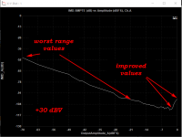
Another issue, is a kind of artifact at the graph capturing when the output gen rating jumps to the next range (for example -20dBV->0dBV).
It seems that the level of capturing is changing and causes a different graph at this area.
I would realy appreciated if someone give me a help...
I try to capture an IMD-SMPTE vs Amplitude measurement (dB scale) via DTP Tool in dB scale.
At my first effort, I modified an exist dtp file for that purpose.
I inserted as "Data to Captured" the:
- IMD-SMPTE, Ch.A (dB),IMD_A)dB)
- Amplitude, Ch.A (dBFS),OutputAmplitude_A(dBFS) and removed the old ones.
Then, I choosed a X-Y Plot with IMD-SMPTE (dB), Ch.A and Amplitude (dBFS), Ch.A, I saved the dtp file and ran it.
Almost everything went well (see at the end).
But, if I reload this dtp file again, the variables of X-Y Plot have dissipated and IMD-SMPTE vs Amplitude is appeared.
Of course, if you run the routine, data values don't captured.
Another issue, is a kind of artifact at the graph capturing when the output gen rating jumps to the next range (for example -20dBV->0dBV).
It seems that the level of capturing is changing and causes a different graph at this area.
I would realy appreciated if someone give me a help...
Attachments
My mistake was that I changed the Alias name of Derived Data Point (DDP).
For example the DDP IMD_A(dB) has an Alias IMD_A(dB), this alias is the text that presented on X-Y axis.
Because I don't like the text "IMD_A(dB)" but I preffer the "IMD-SMPTE (dB), Ch. A", I changed the Alias text. And the problems begun...
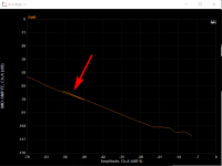
Now I have a right dtp file that works well every time that running (see the capture).
But, I would like to improve it.
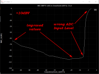
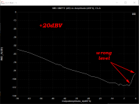
This dtp file opens the psf file \psf\RTX6001\IMD_SMPTE_60Hz(4)_7kHz(1)_FFT131072_RTX6001.psf that has a specific ADC Input Level. Accordingly to this level the precise of IMD measuring changing.
See the attachments files, they are IMD-SMPTE capturing in different ADC Input Levels.
As you can see the low or high level of capturing relates with the input aplitude of ADC.
Here, I prefer to determine the exactly ADC level at the dtp file to have an optimum capturing of IMD.
The manual of Mi-Pro says that the SIR Instruction set the input Range by A-Amplitude (V) area.
This area can be a real number (V) or variable (x1-x5), but I have error with all of that. All the time I have the message "Measuring range not supported"
Any help about this?
For example the DDP IMD_A(dB) has an Alias IMD_A(dB), this alias is the text that presented on X-Y axis.
Because I don't like the text "IMD_A(dB)" but I preffer the "IMD-SMPTE (dB), Ch. A", I changed the Alias text. And the problems begun...
Now I have a right dtp file that works well every time that running (see the capture).
But, I would like to improve it.
This dtp file opens the psf file \psf\RTX6001\IMD_SMPTE_60Hz(4)_7kHz(1)_FFT131072_RTX6001.psf that has a specific ADC Input Level. Accordingly to this level the precise of IMD measuring changing.
See the attachments files, they are IMD-SMPTE capturing in different ADC Input Levels.
As you can see the low or high level of capturing relates with the input aplitude of ADC.
Here, I prefer to determine the exactly ADC level at the dtp file to have an optimum capturing of IMD.
The manual of Mi-Pro says that the SIR Instruction set the input Range by A-Amplitude (V) area.
This area can be a real number (V) or variable (x1-x5), but I have error with all of that. All the time I have the message "Measuring range not supported"
Any help about this?
Attachments
Last edited:
@lemon, thank you for your questions.
As you have already figured out, the aliases of the DDPs to be captured “IMD-SMPTE, Ch.A (dB)” and “IMD-SMPTE, Ch.B (dB)” contain a comma “,”, which happens to be the control character in a DTP file (a Comma Separated Variable (CSV) file). It interferes with the data parsing process when loading a DTP file. We have thus tightened the input validation of the Alias edit box in the DTP configuration panel in the next version. Thank you so much for your finding.
Your DTP uses a fixed Input Ranges for varying output voltage. It does not contain an auto ranging function for optimum distortion performance. Although it is possible to implement an auto ranging function by explicitly specifying the Input Range of RTX6001, the number of steps required will be much more than a DTP using a variable based method instead (see attached).
The attached DTP uses Variable x3 for the output voltage of the DUT and Variables x1 and x2 for the Input Ranges of the two input channels of RTX6001. It contains an auto-ranging function. The auto-ranging function starts the Input Range of RTX6001 from the lowest one: 0.1414V, conducts a trial run (the two "sio*" steps. The first one is used to actually switch the Input Range. It allows RTX6001 to become stable after the possible relay switching before the trial measurement is performed by the second one) and steps up by 10dB (the RTX6001’s attenuation incremental) if the measured PeakLeveldBFS in the trial run is greater than -3dB. The last “SIO” step is the real measurement and only the DDPs obtained in this step are used for the X-Y Plots.
When the SIR instruction is used, the input range value must be within 5% of the hardware supported, otherwise, "Measuring range not supported” error message will pop up. Please also note that the SIR instruction does not actually switch the Input Range until a SIO or STI instruction is implemented.
It should be reasonable to expect some small difference in distortions when the same test tone with the same amplitude output or input using different voltage ranges of RTX6001.
As you have already figured out, the aliases of the DDPs to be captured “IMD-SMPTE, Ch.A (dB)” and “IMD-SMPTE, Ch.B (dB)” contain a comma “,”, which happens to be the control character in a DTP file (a Comma Separated Variable (CSV) file). It interferes with the data parsing process when loading a DTP file. We have thus tightened the input validation of the Alias edit box in the DTP configuration panel in the next version. Thank you so much for your finding.
Your DTP uses a fixed Input Ranges for varying output voltage. It does not contain an auto ranging function for optimum distortion performance. Although it is possible to implement an auto ranging function by explicitly specifying the Input Range of RTX6001, the number of steps required will be much more than a DTP using a variable based method instead (see attached).
The attached DTP uses Variable x3 for the output voltage of the DUT and Variables x1 and x2 for the Input Ranges of the two input channels of RTX6001. It contains an auto-ranging function. The auto-ranging function starts the Input Range of RTX6001 from the lowest one: 0.1414V, conducts a trial run (the two "sio*" steps. The first one is used to actually switch the Input Range. It allows RTX6001 to become stable after the possible relay switching before the trial measurement is performed by the second one) and steps up by 10dB (the RTX6001’s attenuation incremental) if the measured PeakLeveldBFS in the trial run is greater than -3dB. The last “SIO” step is the real measurement and only the DDPs obtained in this step are used for the X-Y Plots.
When the SIR instruction is used, the input range value must be within 5% of the hardware supported, otherwise, "Measuring range not supported” error message will pop up. Please also note that the SIR instruction does not actually switch the Input Range until a SIO or STI instruction is implemented.
Another issue, is a kind of artifact at the graph capturing when the output gen rating jumps to the next range (for example -20dBV->0dBV).
It seems that the level of capturing is changing and causes a different graph at this area....
It should be reasonable to expect some small difference in distortions when the same test tone with the same amplitude output or input using different voltage ranges of RTX6001.
Attachments
Last edited:
- Status
- This old topic is closed. If you want to reopen this topic, contact a moderator using the "Report Post" button.
- Home
- Group Buys
- GB for Virtins MI Pro for RTX6001 autoranging/autoscaling & for soundcard end users