This Bode plot measurement device test plan using RTX6001 will be included in the next release. The method here is generic but the sampling rate, sampling duration and FFT size in the PSF files, and the autoranging criteria (step up when the measured peak level > -0.01dBFS, step down when the measured peak level < -13dBFS) in the device test plan is specific to RTX6001. RTX6001's input ranges are 10dB apart, so the autoranging is programmed based on that. Any hardware that is supported by MI can be used for this type of Bode plot measurement. Thanks to the autoranging function, the hardware does not have to have a big dynamic range at any single input range.
NI DAQmx cards are supported in MI, but Digilent analog discovery does not seem to use NI DAQmx. So it is not supported by MI for the time being.
NI DAQmx cards are supported in MI, but Digilent analog discovery does not seem to use NI DAQmx. So it is not supported by MI for the time being.
1) I try this with XLR output and works without error but I see at the three .psf files that the ADC A/B Coupling Type is a DC and not AC, is that right?
2) The previous testing that I had was with SE output, if the new test is with XLR, please clarify the connection.
Hot -> via capacitor to Vin
Cold -> ?
GND -> ?
2) The previous testing that I had was with SE output, if the new test is with XLR, please clarify the connection.
Hot -> via capacitor to Vin
Cold -> ?
GND -> ?
The error message "Value should be within 0~7.07V" implies that [Setting]>[DAC Device]>”Differential” has been unticked so it does not allow an output amplitude of 10 VAC. For single-ended connection, change the “10”V to “7”V in Step 4. The easiest way to change it is through Windows Notepad. Here is the updated device test plan. It works for both differential and single-ended connections.
Yes, you are right, thanks. In the PSF files, "DC" should be changed to "AC". They have been corrected in the attached files as well.
Single-ended Connection:
RTX6001 GND -> PSU GND
RTX6001 output hot -> via capacitor to PSU Vin
RTX6001 output cold -> Not connected
RTX6001 input hot -> PSU Vin or Vout
RTX6001 input cold -> PSU GND
Differential Connection (Prerequisite: either RTX6001 or PSU is isolated from the mains PE, so there is no direct connection between RTX6001 GND and PSU GND):
RTX6001 GND -> Not connected
RTX6001 output hot -> via capacitor to PSU Vin
RTX6001 output cold -> PSU GND
RTX6001 input hot -> PSU Vin or Vout
RTX6001 input cold -> PSU GND
Attachments
Hi Virtins,
My apologize for the big feedback delay, but a serious health problem kept me a long away from my hobiy.
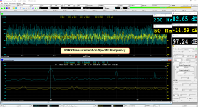
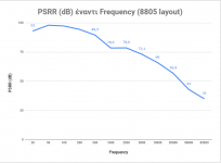
Here I am now and I tried the new PSRR Measurement on a specific LT3042 layout board.
In fact, your test works really good with automation and there is a little difference vs the manual plot testing with sine on Specific Frequencies.
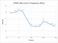
For the manual measurement, I took the difference of the two input ADC (see the attachment file).
My congrats for this new test!
My apologize for the big feedback delay, but a serious health problem kept me a long away from my hobiy.
Here I am now and I tried the new PSRR Measurement on a specific LT3042 layout board.
In fact, your test works really good with automation and there is a little difference vs the manual plot testing with sine on Specific Frequencies.
For the manual measurement, I took the difference of the two input ADC (see the attachment file).
My congrats for this new test!
Attachments
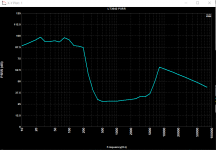
The test here is with LT3042 again, but with a different input pcb layout than previous test.
The auto measurement has a difference (specially to the mid frequencies) vs manual measurement on specific frequencies and manually attenuation of ADC and DAC Output.
The method of manual measurement here is the identical with those of the previous message.
The auto measurement has a difference (specially to the mid frequencies) vs manual measurement on specific frequencies and manually attenuation of ADC and DAC Output.
The method of manual measurement here is the identical with those of the previous message.
Attachments
there is a little difference vs the manual plot testing with sine on Specific Frequencies.
For the manual measurement, I took the difference of the two input ADC (see the attachment file).
Hi Lemon,
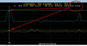
Thank you for sharing your PSRR test results. The PSRR test plan in my Post # 585 uses the peak frequency detected in Ch. A and Ch. B for gain and phase calculation. Unfortunately, in your 200Hz manual test, 200Hz peak frequency was correctly detected in Ch. A, but in Ch. B, 50Hz hum was detected instead as it has the highest amplitude. It is even higher than the 50Hz hum in Ch. A. So it looks like Ch. B was interfered externally.
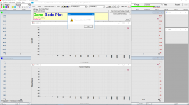
There is another way to do the Bode Plot (as attached). In this method, the spectrum analyzer is set to Transfer Function measurement mode, and the DDPs used are “GainAtGeneratedFreq(dB)”and ”PhaseAtGeneratedFreq(D)”. As their names suggested, the gain and phase in this method are obtained from the generated test frequency instead of the detected peak frequency.
If the generated test frequency is detected as the peak frequency in both Ch. A and Ch. B, then both methods are correct. Otherwise, only the new method will still be correct.
Attachments
Thank you for your interest in Multi-Instrument. You can download the software from www.virtins.com/MIsetup.exe and try it out with full functionality during the 21-day trial period. If you have any questions or suggestions, you can post them here.I’m looking for a audio measurement suite much like Audio Analyzer for the Analog Discovery, and similar in setup and use (simple and straight forward) to compliment my RTX6001. Would MI Pro fit the bill?
A request to forum section moderator - could this thread be split from about message #300 forward and put under "Software tools" section. GB ended a long time ago and it seems out of place to keep discussing the MI here in this section - the discussion is interesting and relevant to MI - just not under GB anymore.
Thank you for your interest in Multi-Instrument. You can download the software from www.virtins.com/MIsetup.exe and try it out with full functionality during the 21-day trial period. If you have any questions or suggestions, you can post them here.
Thanks!
I've been tinkering with it for the past hour, but can't seem to generate similar graphs as shown in the attached image. How would I go about doing that?
Attachments
Hi Lemon,
Thank you for sharing your PSRR test results. The PSRR test plan in my Post # 585 uses the peak frequency detected in Ch. A and Ch. B for gain and phase calculation. Unfortunately, in your 200Hz manual test, 200Hz peak frequency was correctly detected in Ch. A, but in Ch. B, 50Hz hum was detected instead as it has the highest amplitude. It is even higher than the 50Hz hum in Ch. A. So it looks like Ch. B was interfered externally.
There is another way to do the Bode Plot (as attached). In this method, the spectrum analyzer is set to Transfer Function measurement mode, and the DDPs used are “GainAtGeneratedFreq(dB)”and ”PhaseAtGeneratedFreq(D)”. As their names suggested, the gain and phase in this method are obtained from the generated test frequency instead of the detected peak frequency.
If the generated test frequency is detected as the peak frequency in both Ch. A and Ch. B, then both methods are correct. Otherwise, only the new method will still be correct.
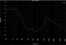
Thanks Virtins, for this upgrade files.
Now the measurement is more precisely with the manual measurement.
At the attachment there is a comparison between old and new method on the same pcb LT layout.
Attachments
I would appreciate it if you can provide some guidance on setting MI up to do a THD+N vs. power plot on a single channel (either left or right) using the RTX6001 and a 8R load?
At the MI-Pro that we bought via this GB, we have and the API for the RTX6001.
I don't know if this including at the 21-days trial period, but if it is there, look at the attachment.
I haven't done amplifier measurements until now, because I have concentrated with digital equipment and power supply measurements.
In the MI-Pro software, there is a bar with some shortcuts of the measurements that MI-Pro can to do.
I have note some of these for your purpose.
The dummy load of 8R is external and of course you must to join at the amplifier output.
At the last, at the MI-Pro installation folder there is a pdf file MultiInstrumentManual.pdf that is the manual of the software.
Attachments
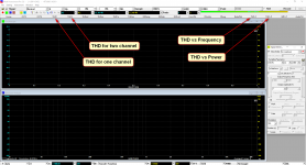
THD to one or two channel, is easy to achieved to the specified frequencies.
The plot THDvsPower is difficult to achieved without API, this test depends steps of gain and attenuation of RTX.
I am not familiar with the Analogue Discovery Audio Analyser Suite and I don't know how this software communicate with the RTX for the gain and attenuate of inputs-outputs to achieve a THDvsPower for example.
I saw an youtube example, how this working and it seems to scpecify to some FFT measurements like thd, imd, FR and thd ploting versus frequency and power.
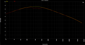
THD+N vs Frequency
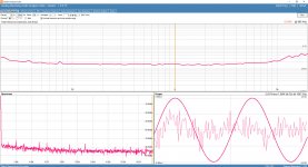
Sorry for the late reply. That graphs is THD+N vs Frequency. It can be done using the Device Test Plan in Multi-Instrument. Device Test Plan provides a mechanism for the users to configure and conduct their own device test steps. Please refer to Chapter 9 of the software manual for details. The software manual can be opened through [help=>[Software Manual] or simply press F1. A quick start guide can be found at: https://www.virtins.com/RTX6001-Multi-InstrumentQuickStartGuide.pdf
In Multi-Instrument, with RTX6001 selected, a sample test plan for THD+N vs Frequency plot can be opened through the "THD~f" button in the third toolbar from the top. In this sample test plan, a Panel Setting File is loaded first using Instruction "LDP" to set the RTX6001 input range and analysis settings. Then Instruction "SIO" is used to step from 20Hz to 20kHz in multiple steps. The output amplitude and frequency are all explicitly specified in each SIO step.
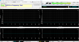
I attach here another way of doing THD+N vs Frequency. Two files:
1. THD+N_Magnitude_vs_Frequency_RTX6001.dtp, to be put under \dtp subdirectory
2. THD_FFT131072_SR48000_10-20200Hz_RTX6001.psf, to be put under \psf\RTX6001
This method uses variables in the test plan with autoranging algorithm. The output frequency and amplitude are implicitly specified by the variables:
x1: output frequency, initialized at Step 4 with a value : 15.625 Hz. It will step up according to 1/3 octave center frequency until 20kHz. The incremental is defined in Step 38.
x2: output amplitude, initialized at Step 5 with a fixed value: 1 V
The screenshot for the loopback test is also attached.]%[/help]
I've been tinkering with it for the past hour, but can't seem to generate similar graphs as shown in the attached image. How would I go about doing that?
Sorry for the late reply. That graphs is THD+N vs Frequency. It can be done using the Device Test Plan in Multi-Instrument. Device Test Plan provides a mechanism for the users to configure and conduct their own device test steps. Please refer to Chapter 9 of the software manual for details. The software manual can be opened through [help=>[Software Manual] or simply press F1. A quick start guide can be found at: https://www.virtins.com/RTX6001-Multi-InstrumentQuickStartGuide.pdf
In Multi-Instrument, with RTX6001 selected, a sample test plan for THD+N vs Frequency plot can be opened through the "THD~f" button in the third toolbar from the top. In this sample test plan, a Panel Setting File is loaded first using Instruction "LDP" to set the RTX6001 input range and analysis settings. Then Instruction "SIO" is used to step from 20Hz to 20kHz in multiple steps. The output amplitude and frequency are all explicitly specified in each SIO step.
I attach here another way of doing THD+N vs Frequency. Two files:
1. THD+N_Magnitude_vs_Frequency_RTX6001.dtp, to be put under \dtp subdirectory
2. THD_FFT131072_SR48000_10-20200Hz_RTX6001.psf, to be put under \psf\RTX6001
This method uses variables in the test plan with autoranging algorithm. The output frequency and amplitude are implicitly specified by the variables:
x1: output frequency, initialized at Step 4 with a value : 15.625 Hz. It will step up according to 1/3 octave center frequency until 20kHz. The incremental is defined in Step 38.
x2: output amplitude, initialized at Step 5 with a fixed value: 1 V
The screenshot for the loopback test is also attached.]%[/help]
Attachments
Last edited:
Now the measurement is more precisely with the manual measurement.
@lemon, thanks for sharing the results. Did you mean "Auto"? The graph seems to be generated using the auto method.
- Status
- This old topic is closed. If you want to reopen this topic, contact a moderator using the "Report Post" button.
- Home
- Group Buys
- GB for Virtins MI Pro for RTX6001 autoranging/autoscaling & for soundcard end users